Author Topic: building BNC cables to measure ripple  (Read 11740 times)

0 Members and 1 Guest are viewing this topic.

frank10

  • Guest
building BNC cables to measure ripple
« on: February 01, 2017, 06:34:31 pm »
I want to measure power ripple from my power supply with a better accuracy, so I saw Dave's video in which he says to build 2x BNC cables, terminated 50 Ohm + capacitor to block DC, to use like differential method.

A similar schema here: https://www.eevblog.com/forum/blog/eevblog-594-how-to-measure-power-supply-ripple-noise/msg409879/#msg409879

So, I'll use RG54 cable with BNC crimped connector. For the resistor, must be exactly 50 ohm? I have 1% 51 Ohm rated resistors, that measured with MM gives 52 Ohm: are they good?
Is it sufficient a  single capacitor of 0.1uF?

After that, I will do math A-B (with acquire peak and Bandwidth limit 20M) and set the oscilloscope probe @2x, right?
TIA
 

Offline tautech

  • Super Contributor
  • ***
  • Posts: 29482
  • Country: nz
  • Taupaki Technologies Ltd. Siglent Distributor NZ.
    • Taupaki Technologies Ltd.
Re: building BNC cables to measure ripple
« Reply #1 on: February 01, 2017, 06:55:51 pm »
IMHO there's little need to go to that trouble as it doesn't replicate real PSU use.
Instead, ensure some small load is present, an auto light bulb is good and use the method described in the following post:
https://www.eevblog.com/forum/blog/eevblog-594-how-to-measure-power-supply-ripple-noise/msg409891/#msg409891
Avid Rabid Hobbyist.
Some stuff seen @ Siglent HQ cannot be shared.
 

frank10

  • Guest
Re: building BNC cables to measure ripple
« Reply #2 on: February 01, 2017, 07:06:09 pm »
I haven't said that, but I meant to add also a little load connected to the supply.

But your link uses a real differential probe... I have no one of them and I don't want to buy one at the moment.
Instead the 2 BNC cables are a cheap way to simulate a differential measure I think.

EDIT: they say P6046 or equivalent.
Does that config work even with two normal probes in A-B Math? With equal good results?

« Last Edit: February 01, 2017, 07:24:41 pm by frank10 »
 

Offline tautech

  • Super Contributor
  • ***
  • Posts: 29482
  • Country: nz
  • Taupaki Technologies Ltd. Siglent Distributor NZ.
    • Taupaki Technologies Ltd.
Re: building BNC cables to measure ripple
« Reply #3 on: February 01, 2017, 07:41:05 pm »
I haven't said that, but I meant to add also a little load connected to the supply.

But your link uses a real differential probe... I have no one of them and I don't want to buy one at the moment.
Instead the 2 BNC cables are a cheap way to simulate a differential measure I think.

EDIT: they say P6046 or equivalent.
Does that config work even with two normal probes in A-B Math? With equal good results?
Yes it does use a Differential probe and sorry I should have stated that's not necessary either.
How that test is set up is to minimise any stray EMI affecting the measurement results.
TBH I only use a normal scope probe set to 1:1 and the scope input set to AC coupling...that's all. Maybe a BW limit too but only if needed.
Avid Rabid Hobbyist.
Some stuff seen @ Siglent HQ cannot be shared.
 

Online David Hess

  • Super Contributor
  • ***
  • Posts: 17211
  • Country: us
  • DavidH
Re: building BNC cables to measure ripple
« Reply #4 on: February 01, 2017, 09:03:18 pm »
The differential measurement is important to remove common mode noise between the power supply and oscilloscope grounds.  However the load does not care about that and the differential noise should be much higher.

I usually get by in a way similar to what tautech describes.  I connect a standard oscilloscope x1 or x10 probe to the output to be measured directly using a coaxial connection to the probe tip so no ground lead is used.  The coaxial connection can be made using a short length of coaxial cable with a BNC connector on one end and a BNC to probe tip adapter.

If I need lower noise, then I make a differential connection using two standard oscilloscope x1 probes coaxially connected as above but with a 7A13 or 7A22 differential amplifier.  This can also be done in add and invert mode as frank10 suggests but performance is not as good as a dedicated differential amplifier or probe like a P6046.  If add and invert mode is used, then trim the low frequency common mode rejection with one of the two vertical variable controls.
 

frank10

  • Guest
Re: building BNC cables to measure ripple
« Reply #5 on: February 03, 2017, 10:22:11 am »
I think the minimum is: shortest GND connection, 1x, BW 20M, I've seen this video: in which the ripple goes down upto 1/12 (15mV to 1.2mV) !
Caps should also clean the HF signal.

These are also my first oscilloscope's measurements...  ;)
I tried to measure 2 switching power supply and one notmore-regulated linear one.

Anyway, the rough impression is I need some less noisy, more precise measure with one of the switching that is noisy, I hope to get it with caps, but also with BNC cables or something differential (not real differential probes).

So:
1) normal probe, short GND, 1x, BW 20M --> ok
2) I made a simple short BNC, RG58 cable without termination. I tried both this cable and also another test with a single probe without GND connected as David suggested --> strange distorted signal AC 67V (!!??)...
if I connect V- with GND of a probe in Ch2, signal becomes ok, like 1), BUT with enormous values, like 530mV instead of 50mV (ripple+noise) regards normal probe 1).

https://youtu.be/Wj_rOCtMeKw

3) I tried 2 probes, one on V+ the other to V-, gnd, with the tips, no GND connected: in both CH1 and CH2 I got the same signal as 2, Math A-B don't do it correct obviously.
4) in one power switching I get classic ripple signal, but in the (cheap 50€) bench one I get an oscillating AC wave (about 77kHz) different from "normal" ripple, look at the previous video @2'32'' . What is this? Not good filtering out of ali?

« Last Edit: February 03, 2017, 04:14:56 pm by frank10 »
 

Offline tautech

  • Super Contributor
  • ***
  • Posts: 29482
  • Country: nz
  • Taupaki Technologies Ltd. Siglent Distributor NZ.
    • Taupaki Technologies Ltd.
Re: building BNC cables to measure ripple
« Reply #6 on: February 03, 2017, 11:41:23 am »
You are looking for repetitive waveforms so turn on some averaging and that will clean up some of the spurious muck.  ;)
Avid Rabid Hobbyist.
Some stuff seen @ Siglent HQ cannot be shared.
 

frank10

  • Guest
Re: building BNC cables to measure ripple
« Reply #7 on: February 03, 2017, 12:33:05 pm »
Yes, I tried also that (I tested all modes: normal, peak, average, high res), yes average lowers noise pikes, but Dave suggested to use peak mode to get correct ripple.
Anyway it doesn't change that much: it goes from 820mV to 500mV...

Anyway the highres/average thing it's a relative problem, as it's there quite almost when on 50-20mV/20-10ms scale: when I zoom in to 5-10mV/5-1us the peak noise are quite gone, after freezing, even in high res mode, so not a real problem.

The problem is the so much different scale between BNC probe or normal probe with a ch2 ground connection (apart the major prob of 67V without gnd??). It's a 10:1 difference!
« Last Edit: February 04, 2017, 10:49:16 am by frank10 »
 

Online David Hess

  • Super Contributor
  • ***
  • Posts: 17211
  • Country: us
  • DavidH
Re: building BNC cables to measure ripple
« Reply #8 on: February 03, 2017, 06:40:16 pm »
2) I made a simple short BNC, RG58 cable without termination. I tried both this cable and also another test with a single probe without GND connected as David suggested --> strange distorted signal AC 67V (!!??)...
if I connect V- with GND of a probe in Ch2, signal becomes ok, like 1), BUT with enormous values, like 530mV instead of 50mV (ripple+noise) regards normal probe 1).

I was not clear enough.  A coaxial probe tip connection *includes* ground as the outside connector.  The ground lead of the probe is not used in this case and the coaxial connection shields the signal.

https://www.eevblog.com/forum/projects/probe-tip-to-bnc-adapter/

http://www.testpath.com/Items/Adapter-Male-BNC-to-5mm-Probe-Tip-Unterminated-123-547.htm
http://www.digikey.com/product-detail/en/teledyne-lecroy/PP005-BNC/PP005-BNC-ND/3587091
https://www.picotech.com/accessories/passive-oscilloscope-probes/probe-tip-to-bnc-adaptor
 

frank10

  • Guest
Re: building BNC cables to measure ripple
« Reply #9 on: February 03, 2017, 07:11:02 pm »
Ah, ok, sorry for the BNC, my bad, I'm newby on oscilloscope... So you can use:
BNCtoProbe + BNC-banana adapter    or   BNCtoProbe + short BNC-BNC cable ?

Anyway, the (poor-man) differential method, as seen also in Dave's video with normal probes, should be made connecting only the 2x probe's tip without any GND connection to V+ and V-, right? Does it need some 50 Ohm termination on oscilloscope's BNC input? (I saw Dave put it on the analog oscilloscope, I don't know if needed in the digital one, too...).

BTW, I have some old BNC connectors I bought when I made some 75 Ohm cables. Do these connector work also on 50 Ohm? Or is it needed to buy a specific 50 Ohm BNC connector? Or are they both good for 50/75 Ohm?


Online David Hess

  • Super Contributor
  • ***
  • Posts: 17211
  • Country: us
  • DavidH
Re: building BNC cables to measure ripple
« Reply #10 on: February 04, 2017, 12:04:42 am »
Ah, ok, sorry for the BNC, my bad, I'm newby on oscilloscope... So you can use:
BNCtoProbe + BNC-banana adapter    or   BNCtoProbe + short BNC-BNC cable ?

I use oscilloscope or test instrument -to- probe -to- coaxial probe tip to BNC adapter -to- BNC female-to-female -to- short BNC male terminated cable to test point and ground.

Quote
Anyway, the (poor-man) differential method, as seen also in Dave's video with normal probes, should be made connecting only the 2x probe's tip without any GND connection to V+ and V-, right? Does it need some 50 Ohm termination on oscilloscope's BNC input? (I saw Dave put it on the analog oscilloscope, I don't know if needed in the digital one, too...).

Sometimes this can work but the common mode voltage between the differential input and the device under test has to be within the input range of the test instrument.  DSOs have more problems with this than analog oscilloscopes because the subtraction *adds* the quantization noise from each channel together.

Quote
BTW, I have some old BNC connectors I bought when I made some 75 Ohm cables. Do these connector work also on 50 Ohm? Or is it needed to buy a specific 50 Ohm BNC connector? Or are they both good for 50/75 Ohm?

They will work fine.  One cheap place to find suitable BNC pigtails is to cut up an old RGB video cable and they are often 75 ohm RG-179.  Since the BNC cable pigtail is short and the source impedance is low, the cable impedance and unterminated capacitance are unimportant.
 

frank10

  • Guest
Re: building BNC cables to measure ripple
« Reply #11 on: February 04, 2017, 01:38:27 pm »
@tautech
with another ali switching it was really huge the amount of noise with peak! Definitely Highres was a lot better, of course average even less noise. So, yes, depending on DUT, average could make a lot of difference.

So, I made another BNC cable with 52 Ohm (rated 51) termination + another 52 in series + the capacitor to block DC (without it will also flow 0,11A...), used @2x and I compared it to the normal probe @1x also with capacitor.
(It remains my first question: can I use 52 Ohm  terminating , or should I really sum measured resistors to get perfectly 50 Ohm or making parallel ie 3x150 ohm?)

Then I made the same with the other BNC cable not terminated @1x.
Well, I don't see differences... apart 1,5-4mV between the three method. Noise is equal, too.

I made comparison also between AC coupling and DC coupling (I read it was more sensitive), now that I put the capacitor, but no difference.

No load this time, next test + HF filter caps.
Here some pics. (CH1 BNC without termination, CH2 with termination, CH4 probe)


« Last Edit: February 04, 2017, 06:16:23 pm by frank10 »
 

Offline tautech

  • Super Contributor
  • ***
  • Posts: 29482
  • Country: nz
  • Taupaki Technologies Ltd. Siglent Distributor NZ.
    • Taupaki Technologies Ltd.
Re: building BNC cables to measure ripple
« Reply #12 on: February 04, 2017, 06:12:34 pm »
When chasing mV's one needs to ask: are they really there and do they really matter ?

Some will be internal scope noise, some the measurement techniques capturing other EMI that can come from a myriad of sources and some the real PSU noise.
Also check the noise floor of your scope by terminating the inputs with a 50 \$\Omega\$ terminator.

For SMPS, the frequency that the SMPS controller works at will be the frequency of interest where the reals PSU noise is, for linear the noise and ripple frequency should be @ 2x your mains frequency so how you set your scope is very relevant to what you're trying to measure. Remember I mentioned focussing on noise of repetitive frequency not just all the muck that your screen displays.
DSO's seem noisy but it's how you interpret what you see onscreen and what UI features you use to get the real info you're looking for.
Have a look for Daves 2 vids on Why DSO's appear to be noisy?

PSU noise components that matter will be under a few 100 KHz and remove the DC component by using AC coupling only.

 
Avid Rabid Hobbyist.
Some stuff seen @ Siglent HQ cannot be shared.
 

frank10

  • Guest
Re: building BNC cables to measure ripple
« Reply #13 on: February 04, 2017, 07:24:57 pm »
When chasing mV's one needs to ask: are they really there and do they really matter ?
Have a look for Daves 2 vids on Why DSO's appear to be noisy?
Yes, I saw that one!

Quote
for linear the noise and ripple frequency should be @ 2x your mains frequency so how you set your scope is very relevant to what you're trying to measure.
I saw this on a bad ex-regulated linear power supply
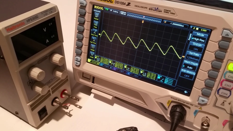
There is the regular frequency @100Hz, but no noise at all: does this mean I have a very clean mains line?
"so how you set your scope is very relevant": what do you mean? How should it be set?

Quote
PSU noise components that matter will be under a few 100 KHz and remove the DC component by using AC coupling only.
Ok, I did, but I'm finding difficult to read the real ripple, as it's a different shape other than classic of i.e. the linear transformer of previous pic1.
Let's see another "normal" ripple of a portable power switching @12V:

There is the classic ripple shape and this time there is noise on the peak quite every 100Hz, not so precise. Why here there is the noise @100Hz and in the linear transformer not?
I measured it @13mV, noise repetitive peaks are about 300mV.
Frequency this time is oscillating and not multiple of 50Hz: it's about 83Hz.
Anyway this shapes are easy to measure...

Instead look at these other two power switching:
1)

 has a frequency of 77kHz and it goes also under the "0 line" like a real complete AC wave. This time the ripple is the complete big wave pp apart the sporadic noise peaks at the rising of the wave, or only an average of it under the big beginning of the wave?
I measured the big wave @30mV-46mV. It's also not regular and constant like the previous...
And this one should have a declared spec of <0.5mVrms !! Even measuring it in Vrms they are 7-8mVrms, not 0.5!
Or maybe I'm not using perfect probe measurements, that's a reason I would like to try the pseudo differential method, with no luck... next posts...
EDIT:
I made also this zoomed snapshot from oscillo + params in the attachements:


2) Anyway, look at this other power switching for minipc:


it has a frequency of 100Hz, a lot noisy, but very different from pic2...
And here what should be the ripple? The great big noisy wave at 100Hz pp, or only the central part between the big waves?
Central part is a good 3.5mV ripple BUT including repetitive spikes, otherwise without them is less than half, about 2mV, but even here it's not that easy to measure, not clear edges...:

instead big pp are about 11-12mV, without spikes:

Which one?

You will tell me: put average!
Well, I did but this time did'nt solve a lot... it was again a lot peaky, not easy to measure...:


All @12V DC without load. Imagine with load!


PS @webmaster:
it should be better to alert the poster when he's inserting attachments for the 2Mb limit, not after he posted and then return back to insert all pics again...

PS2:
is there a way to insert attachments pics inline with text? It should be a lot better. Otherwise one should upload them on another server and then put the link: better if possible inside the forum itself.

EDIT:
ok, thanks to tautech's suggest it's possible to put attachment inline, but it should be better to make an automated procedure like in other forums, avoiding copy and paste of addresses. More, in the modify you can't read the adresses, so you must keep a browser's tab open to copy them into the other modify tab... a bit tricky.
« Last Edit: February 06, 2017, 09:59:30 am by frank10 »
 

Offline tautech

  • Super Contributor
  • ***
  • Posts: 29482
  • Country: nz
  • Taupaki Technologies Ltd. Siglent Distributor NZ.
    • Taupaki Technologies Ltd.
Re: building BNC cables to measure ripple
« Reply #14 on: February 04, 2017, 08:07:39 pm »
You are limited to the forum's 2Mb limit BUT scope screenshots to a USB stick are only a few 10's of Kb's and offer much more info about your scope settings. Learn how to do these and add them to your posts as Attachments where they become thumbnails just like pics but because they are much smaller are faster to upload and for us to view.

Then "Modify" your post after "Copy"ing the thumbnail address and insert that address within the text body of your post. Then highlight it with your mouse and select the Insert Image button after which the address will be within IMG quotes.
Sometimes if you want to add several images to your text body it require multiple "Modifiy" 's.  ;)
Avid Rabid Hobbyist.
Some stuff seen @ Siglent HQ cannot be shared.
 

Offline tautech

  • Super Contributor
  • ***
  • Posts: 29482
  • Country: nz
  • Taupaki Technologies Ltd. Siglent Distributor NZ.
    • Taupaki Technologies Ltd.
Re: building BNC cables to measure ripple
« Reply #15 on: February 04, 2017, 08:35:16 pm »
Quote
All @12V DC without load. Imagine with load!
Ripple measurements are always better with some load. (light not excessive, say 50 to 500mA)
Most PSU's ripple will rise as full load is neared/applied.

Now I've used the word "real" a few times: Hint, take measurements at the load where any ripple present might or might not affect a circuit. Don't forget to add some bulk capacitance like in a real circuit. I use 1000uF low ESR.

Edit
I'll examine you pics later as my internet is slow ATM.
Avid Rabid Hobbyist.
Some stuff seen @ Siglent HQ cannot be shared.
 

Online JPortici

  • Super Contributor
  • ***
  • Posts: 3527
  • Country: it
Re: building BNC cables to measure ripple
« Reply #16 on: February 04, 2017, 08:50:09 pm »
two things if you were not aware:
switching power supplies don't like loads much lower than their rated current: the regulator may skip pulses in order to stay at the regulated voltage level, that will change many things.
this is the reason why there is a minimum load requirements on most switchers, which may or may not be present!
+1 on screenshots. you have a DSO!!!!
please notice that the 1054z will go nuts if you use a usb stick > 2 GB
 

Offline tautech

  • Super Contributor
  • ***
  • Posts: 29482
  • Country: nz
  • Taupaki Technologies Ltd. Siglent Distributor NZ.
    • Taupaki Technologies Ltd.
Re: building BNC cables to measure ripple
« Reply #17 on: February 04, 2017, 08:51:57 pm »
Check this thread for further understanding and examples of what can be seen:
https://www.eevblog.com/forum/chat/show-me-your-psu-noise/
Avid Rabid Hobbyist.
Some stuff seen @ Siglent HQ cannot be shared.
 

frank10

  • Guest
Re: building BNC cables to measure ripple
« Reply #18 on: February 04, 2017, 08:56:53 pm »
Thank you tautech, I modified my post to put pics inline, a bit tricky... should be improved.

For the load, I'll try to do like your previous linked schema
https://www.eevblog.com/forum/blog/eevblog-594-how-to-measure-power-supply-ripple-noise/msg409891/#msg409891

+ another parallel 1000uF cap: the third, after the one 0.1uF, near the load?


I'll do the load thing, but before I wanted to solve the best probe method, cause I don't want to repeat all tests ;)

So, after some comments on these pics, I'll ask again on the differential method.


I'll check your link, thanks.


@JPortici
Thanks, I'll do the load, but I can't put such a big resistive load, my bench is 30V 5A... the other switch is 12V10A! The only one I could test with near full load is the small 12V portable switch, but that is just already pretty clean ripple signal...
Anyway, I'll do the tautech's relative small load.

I'll do the USB thing.

Anyway I made the pics, because I recorded the videos, so they are extracted from it... ;)
 

Offline tautech

  • Super Contributor
  • ***
  • Posts: 29482
  • Country: nz
  • Taupaki Technologies Ltd. Siglent Distributor NZ.
    • Taupaki Technologies Ltd.
Re: building BNC cables to measure ripple
« Reply #19 on: February 04, 2017, 09:13:06 pm »
Quote
EDIT:
ok, thanks to tautech's suggest it's possible to put attachment inline, but it should be better to make an automated procedure like in other forums, avoiding copy and paste of addresses. More, in the modify you can't read the adresses, so you must keep a browser's tab open to copy them into the other modify tab... a bit tricky.
That's how it is here, accept it and learn to work with it.
Detailed posts do take some "crafting and effort" but once you've done a few it's pretty easy.

That edit looks fine except we can't see the detail of exactly how you scope is set, screenshots are much better.  ;)
Avid Rabid Hobbyist.
Some stuff seen @ Siglent HQ cannot be shared.
 

frank10

  • Guest
Re: building BNC cables to measure ripple
« Reply #20 on: February 04, 2017, 09:16:40 pm »
That's how it is here, accept it and learn to work with it.
Detailed posts do take some "crafting and effort" but once you've done a few it's pretty easy.
Yes, of course, it's not a concern or a rant: only suggestion to improve things :)
 

Offline bingo600

  • Super Contributor
  • ***
  • Posts: 2034
  • Country: dk
Re: building BNC cables to measure ripple
« Reply #21 on: February 05, 2017, 09:42:45 am »
Then "Modify" your post after "Copy"ing the thumbnail address and insert that address within the text body of your post. Then highlight it with your mouse and select the Insert Image button after which the address will be within IMG quotes.
Sometimes if you want to add several images to your text body it require multiple "Modifiy" 's.  ;)

I postprocess the images to PNG after getting them from the USB stick, they take up a lot less bandwidth to load.
And doesn't seem to degrade noticeably.

But it didn't know that the Rigol would FSCK'up if using more than 2G USB.Stick. (Thanx)
I usually get the images via Lan.

/Bingo
 

Offline 3db

  • Frequent Contributor
  • **
  • Posts: 331
  • Country: gb
Re: building BNC cables to measure ripple
« Reply #22 on: February 05, 2017, 09:52:40 am »
Regarding the 50 ohm resistors.
I think you should just buy some 50 ohm terminators and a T piece  or two.
They will come in handy for future use.

3DB
 

frank10

  • Guest
Re: building BNC cables to measure ripple
« Reply #23 on: February 05, 2017, 11:17:29 am »
I postprocess the images to PNG after getting them from the USB stick, they take up a lot less bandwidth to load.
And doesn't seem to degrade noticeably.

/Bingo

png is lossless, so you won't loose anything.
Anyway jpg can make lighter pics already very good looking, it all depends on compression percentage.
« Last Edit: February 06, 2017, 08:12:55 am by frank10 »
 

Offline tautech

  • Super Contributor
  • ***
  • Posts: 29482
  • Country: nz
  • Taupaki Technologies Ltd. Siglent Distributor NZ.
    • Taupaki Technologies Ltd.
Re: building BNC cables to measure ripple
« Reply #24 on: February 05, 2017, 07:47:58 pm »
Then "Modify" your post after "Copy"ing the thumbnail address and insert that address within the text body of your post. Then highlight it with your mouse and select the Insert Image button after which the address will be within IMG quotes.
Sometimes if you want to add several images to your text body it require multiple "Modifiy" 's.  ;)

I postprocess the images to PNG after getting them from the USB stick, they take up a lot less bandwidth to load.
And doesn't seem to degrade noticeably.

But it didn't know that the Rigol would FSCK'up if using more than 2G USB.Stick. (Thanx)
I usually get the images via Lan.

/Bingo
Quite right Bingo but all the OP's images thus far have been phone photos captured from a vid not screenshots that are generally less than 50Kb. However lots of detail from how the scope is set is hard to read or missing.
« Last Edit: February 05, 2017, 07:49:50 pm by tautech »
Avid Rabid Hobbyist.
Some stuff seen @ Siglent HQ cannot be shared.


Share me

Digg  Facebook  SlashDot  Delicious  Technorati  Twitter  Google  Yahoo
Smf