Great, more 2465B owners.

A couple of quick comments...
The measurement screen looks normal to me. The same as I see on mine.
The knob gaps look normal to me too - typical of the dozens of these scopes I've seen and used over the years.
The calibration waveform looks exactly like that on my scope if I use the Auto function. On these scopes, the calibration signal frequency varies with the horizontal timebase setting. You would typically use the cal signal to adjust the compensation of your 10x probes. However, in order to do that, you'll probably want to adjust the timebase to something between 200us to 1ms / div. For more info on 10x probes and their compensation, you might want to check out this video:
Thanks for the confirmations on the knobs and auto measurement result, I feel qute happy now. About those knob gaps, again, since this is my first Tek, so I was sort of suspecting whether it was refurbished and tampered before, cause it looks like those knobs are not installed properly, I guess Tek didn't care bout these minor details.

And yeah, I had my probe's compensation calibrated already, also again, thanks for the video !
This seems to be quite common among 2445B and 2465B models. Earlier models don't seem to have this quirk. And even not all B models have it. I have one 2465B that has this flicker as well and I have another one that doesn't. Maybe it's a firmware difference. I was planning to investigate this a little further myself but haven't found the time yet. The LEDs are driven via a serial to parallel shift register. It shouldn't be that hard to hook up a logic analyzer on the serial input and clock lines of the shift register and see if the firmware is actually commanding the LEDs to "flicker" or not.
Another great information, thank you, so its normal, breathed a sigh of relief.
Yeah, probably some changes at the firmware between both, since you have two 2465B there, are both have the same ROM version ? Btw, mine is Guernsey made.
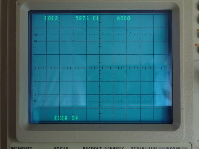
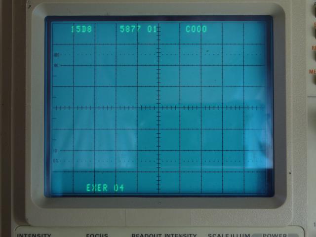
Here is mine, accessed through diagnostic excercise routine at EXER 04 to show the rom info, and the codes occupied at 3 locations, and all are version "01", whats yours ? Especially at the one that flickers ?
1st location
2nd location
3rd location

PS: if you open up your scope check out the vertical PCB on the side (the A5 PCB if you have the service manual). If your version is built with SMD components then you need to replace the electrolytic capacitors on this board. I think there are 4 or 5 of them. They are known to leak and the electrolyte will sooner or later destroy the board beyond repair. There is much info on this on the TekScopes yahoo group. If your A5 board is an earlier version built with trough hole components then you have nothing to worry about.
My A5 board is SMD version, it has only 2 electrolytic caps, other are tantalums. Yeah, I'm aware of that leaky cap especially the smd version at A5 board from yahoo tekscope group, and strange part is it has only 2 instead of 4 or 5 as yours ?

I'm planning to do a complete re-cap at all electrolytic type in this scope, and also few non electrolytic type if I'm not mistaken that are in the power supply section, that are known to crack and cause trouble. Any more tips or hints on the re-cap ?
The A5 control & logic board, 4 red circles are the those 7 caps locations, you can see there are only two blue electrolytic caps at the upper right red circle :

Close up at the upper right circle, two electrolytic caps and 2 black tantalum, these tantalum won't leak right ? Or they're known to cause trouble as well ?

With measurement screen and 4 traces turned on, the text readout position looks fine right ? I mean compared to yours ?
Yes that looks exactly like mine.
Btw would you do me another favor, hook up the probe at the calibration pin as your video, and push the the red "AUTO" button for automatic scale selection on horz and vert adjustment and watch for the result, does yours looks like this below ?
Yes mine is exactly the same, and its normal. On the cal hook you will notice a recommended cal timebase (I mentioned it in the video). The Cal output on the 2465B is a little bit fancy compared to other scopes. On timebase ranges down to 100nSecs the scope automatically changes the cal frequency (You'll notice when I changed the timebase in the video that the display seemed to remain constant). What Tektronix did was to make the cal output frequency such that each half a cycle takes up exactly one horizontal graticule. On many simpler scopes the cal output frequency is fixed (ie 1khz etc) and doesnt change as you adjust the timebase. Taking up one graticule makes it easy to quickly check that your scope is in cal.
So you notice your cal output looks crapy on the 50nSecs range. This is because the timebase setting is below the 100nSec's limit of the cal adjustment. You should not use less than 100nSecs timebases to compensate your cal probes.
Thanks again, at least now I'm sure that my auto is behaving as it should at the cal signal.
Lol, yeah, I was quite surprised and very confused too when I did test the cal signal for the 1st time, cause my previous scope has a fixed frequency, and that was before I read the operational guide, until I noticed and spotted the fine printed label at the cal terminal that says "5 Hz - 5 MHz", have to admit that cal circuit its quite fancy.

Few other questions if you don't mind testing it for me :
- When power up after pressing the power button, during the diagnostic where some of those leds at the panel was blinking, did you hear a single click sound ? It sounds like a relay, and only one time when powered up.
- While pushing buttons or turning any mechanical switch at the panel, at my panel, other leds also flicker a bit too, not much though, only dimly blink when any button pushed or switch turned, does your 2465b front panel leds also experience the same ?
The one click sounds normal. I don't really see blinking in the other leds however someone mentioned above some do this and some not so if so I wouldn't worry about it.
With regard to the startup message "Diagnstic. Push A/B trig to exit", I just had a quick look in the manual and notice that message continues to appear if at some point in the past the scope had failed a startup test. On my scope I can enter the menu by pressing the delta-time and delta-volts buttons simultaneously. When you go into the diagnostic menu you should select exerciser 03 "Cycle Error Clear" to see if you can make that go away. See page 6-18 of the service manual.
good luck.
Hey Gregariz, this solved the problem ! Thank you Sir !
I was heavily concentrated and occupied at those circuits diagrams from the 1st time I got this scope, and only briefly skimmed through the written text part of that service manual. Heck, I even printed all those wide scanned circuit diagrams at A2 sized papers for easy reading

, but not printed the text part yet, go figure.
More questions to 2465B owners :
The power on hours and cycle counts, looks suspiciously low isn't it ? I guess someone did a reset or may be not at all ?

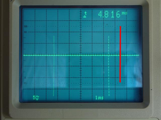
The vertical measurement cursors, both vertical location are not correct right ? I guess they should be at same height as the red line I draw there, how is yours ? Time to hunt down the circuit that handle these vertical position for these cursors, and just fyi, the text readout vertical adjustment as I did previously for fixing the text is not affecting them.
The pic of the notorius, unobtainium U800 or 155-0241-02 hybrid ic , and this toaster is really scorching hot, verified it with my own finger at the ic's black body.

Took a peek under the pcb using bright flashlight, these two bolts are not attached to anything at all under the pcb, or to any metal body/chasis, and they just sort of soldered at the pcb, so the heat dissipation path is only from the metal lid from the ic at the right bolt, and that tiny short bolt is acting as the primary heatsink.

From the power distribution diagram, this poor little ic is working at
+87 V 
, and its the brain of the whole scope's horizontal section, no wonder its easily burned and screwed.
Planning to put a copper heat sink there with a high quality Shin-Etsu non sticky thermal pad, and add two more nuts on top of at that two bolts to fasten the securing steel wire clip, that will hold and press the heatsink at the ic. The problem is I can't find those nuts here locally cause all nut & bolt measurement are using metric system instead of imperial system.
Or I just use a double sided sticky 3M thermal pad, and let the adhesive pad do the work on holding the heatsink ?
Please share if you've done something to cool this chip and what exactly did you do to it ?
.


