Author Topic: Quad photodetector amplifier  (Read 310 times)

0 Members and 1 Guest are viewing this topic.

Offline mr_byte31Topic starter

  • Contributor
  • Posts: 17
  • Country: de
Quad photodetector amplifier
« on: July 12, 2024, 09:47:07 am »
Hi Folks,

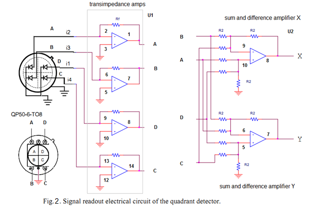
I have a Quad-photodetector and I want to amplify the signal of each quadrant independently but I need to guarantee the same gain for all of them.

I thought about using operational amplifier for each quadrant but I know that the gain is dependant on the resistance values which has minor mismatches due to manufacturing process.
I also need to add and subtract the values after amplifications.


I found some components that can do so ex. LMH32404 and LTC6561. I am just wondering how they are implemented.

any hints how to guarantee a constant gain for each quadrant using  onvthe shelf components ( op-amp, transistors, R, L , C,..etc) ?
 

Offline Positron Enthusiast

  • Newbie
  • Posts: 9
  • Country: us
Re: Quad photodetector amplifier
« Reply #1 on: July 13, 2024, 06:53:47 am »
There’s two easy ways to do this:
Live with the gain error from COTS parts


Make a calibration test fixture to calibrate the gains and linearity for each board and store it on the board in an MCU etc…if you only need relative accuracy between gains/ channels then this is even easier to make.


There are probably hard ways to get more accurate gains off the bat but I dont know how well they work in this application.


What I can say is that option 2 - calibrated gains - works very well at low frequency. A good way to do it would be reed relays to a programmable current source (common to each analog frontend). Step the current source through the gain stages for each amplifier and boom, gains are calibrated. Recalibrate it on a timer or temperature differential. (Say 5-20 deg C depending on application requirement). Analog switches may work depending on system specs. Environmental sensors and mcu are dirt cheap nowadays. The current source can be a DAC feeding opamps. Just take enough averages to get an accurate gain measurement.
 
The following users thanked this post: mr_byte31

Offline dietert1

  • Super Contributor
  • ***
  • Posts: 2273
  • Country: br
    • CADT Homepage
Re: Quad photodetector amplifier
« Reply #2 on: July 13, 2024, 07:03:40 am »
Yes, probably one needs to calibrate the four channels for equal gain, as the detector will also introduce deviations.
Our first series of pulse oximeters had transimpedance amplifiers with adjustable gain. 10 KOhm digital potentiometer chips were used to divide the ampilfier output before feeding the 1 MOhm transimpedance resistor.

Regards, Dieter
 
The following users thanked this post: mr_byte31

Online Kleinstein

  • Super Contributor
  • ***
  • Posts: 14552
  • Country: de
Re: Quad photodetector amplifier
« Reply #3 on: July 13, 2024, 09:14:53 am »
The gain is set by the resistors and sensitivey / area of the detector parts and the optics (e.g. case) in front. The normal 1% resistors should be good enough in most cases. It depends on the application if an extra fine trim af the gain is needed - I see little need for very good  matching. If needed there are resistor arrays with very good matching (e.g. 0.01% ), but this is likely over-kill. 0.05% matching is possibly with the cheap ACAS series (thpough not 1 M).

 
The following users thanked this post: mr_byte31

Offline mr_byte31Topic starter

  • Contributor
  • Posts: 17
  • Country: de
Re: Quad photodetector amplifier
« Reply #4 on: July 15, 2024, 09:32:16 am »
Let me give it a try and measure the errors from low error resistors.


Share me

Digg  Facebook  SlashDot  Delicious  Technorati  Twitter  Google  Yahoo
Smf