-
Hi,
I'm working on a project where I have a square wave of either 0-5V or 0-12V as an input to a SAM3X microcontroller (3.3V logic). The signal(s) will be coming from automotive tachometers and other automotive pulse sources.
Now obviously I can't input that directly and I'm not aware of any 5V tolerant inputs on this chip.
A voltage divider that works for 12V is unlikely to yield good results with a 5V signal connected and vice versa. There is also a possibility that the source will not respond well to being loaded, so I believe a high impedance input may be required.
I've seen suggestions to use a comparator such as an LM339 - it's my understanding that Vcc of the comparator will need to be Vmax (12V) to work, otherwise, if I use say, 3.3V as Vcc then a 12V input on the inverting/non-inverting pin will damage the IC - is this correct or can I actually run Vcc at 3.3V safely?
If I put Vcc at 12V and put a 5V signal into the non-inverting pin, as I understand it I can get a 3.3V signal out due to the open collector output (pull up the output to 3.3V).
What is the best way to convert this voltage range to something safe? -
What frequency is the square wave?
The easiest method is to use a series resistor, say 10k to 1M, before the MCU input. The internal ESD protection diodes will clamp the input voltage at about 0.6V above the MCU's power supply. -
Another alternative is to use a simple NPN transistor as a buffer:
https://cdn.sparkfun.com/r/400-400/assets/learn_tutorials/1/9/3/logic-inverter-circuit.png
If you need some more protection and ground loop isolation, you can use an opto-coupler with the NPN transistor. -
You have to limit current so you do not trigger parasitic SCR
present in CMOS devices. In increasingly numbers that current
spec is in MCU datasheets. Also known as latchup current, although
that can be the Idd once latchup occurs. Read datasheet carefully.
https://en.wikipedia.org/wiki/Latch-up
The trade off is as R goes up, speed drops of this interface due to
RC effects.
Regards, Dana. -
You can use a 74HC4050 or a more sophisticated level shifter.
-
Perhaps you can use a LIN transceiver in receive only mode for this. They are more expensive (while still very cheap) than similar circuit made from discretes, but they are fault protected and characterized. Made for automotive environment.
-
Use a series resistor that is connected to your input. Then at that input put a couple of diodes: one connected to 3.3V, and the other connected to ground.
-
The LM339 has an open-collector output, so I believe you can use that if you have a 12V supply available for its Vcc. Then on the output you would have a pullup resistor to the 3.3V rail.
-
You should consider whether galvanic isolation might be beneficial.
If so, you could combine it with an optocoupler for level translation. -
Use a series resistor that is connected to your input. Then at that input put a couple of diodes: one connected to 3.3V, and the other connected to ground.
Which will conduct first? Those diodes or the internal ESD protection didoes? They should be Schottky diodes to ensure they conduct and not the ones inside the IC. -
BAT54S is a good one for that, SOT package, 2 diodes.
-
Just use a discrete small-signal MOSFET with a drain resistor to +3.3 V. There are automotive types available with gate protection against transients.
Don't forget it will invert the input, but your firmware should take care of that.
-
Just use a discrete small-signal MOSFET with a drain resistor to +3.3 V. There are automotive types available with gate protection against transients.
Or put the resistor between the source and 0V and connect the drain to +3.3V.
Don't forget it will invert the input, but your firmware should take care of that. -
Just use a discrete small-signal MOSFET with a drain resistor to +3.3 V. There are automotive types available with gate protection against transients.
Or put the resistor between the source and 0V and connect the drain to +3.3V.
Don't forget it will invert the input, but your firmware should take care of that.
That would require a MOSFET that turns on at 1.7 V gate voltage, which is not easy to find.
-
No it wouldn't. The logic input doesn't need the full 3.3V to work. The minimum high-level voltage will be something like 2V, so anything with a 3V threshold or less will do. The 2N7002 will do.Just use a discrete small-signal MOSFET with a drain resistor to +3.3 V. There are automotive types available with gate protection against transients.
Or put the resistor between the source and 0V and connect the drain to +3.3V.
Don't forget it will invert the input, but your firmware should take care of that.
That would require a MOSFET that turns on at 1.7 V gate voltage, which is not easy to find. -
If you don't mind signal inversion, with 5V you could just stick a 5V tolerant hex inverter in there.
-
It depends on how fast your signals are, what protection needed and how clean (signal integrity) you need the signal be.
For automotive application interfacing into sensitive equipment, complete galvanic isolation using optocoupler is favored. Considering that automotive 13.8v line can surge to very high voltage at load dump, even peaking at 60V(!)
Otherwise if the source is already surge-suppressed, you can use pretty much any logic level shifter. With comparator, the idea is to pull-up the comparator's open drain/open colector output into target voltage. Obviously the comparator itself is supplied from the (higher) source voltage. Unless specifically noted in the datasheet, never put voltages higher than supply voltage on any IC and expect it to work flawlessly.
For simple shifter, you can also copy Sparkfun's level shifter. You also get bonus that it is bidirectional.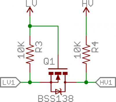
About low voltage MOSFET. Almost all MOSFET Vgs(th) is pretty low in the ~2V area, and even lower for signal MOSFET. You don't need to get past Miller voltage just to conduct a few microamperes. -
Wow, there've been a lot of responses on this so I'll try to address them all - thanks guys!
What frequency is the square wave?
The easiest method is to use a series resistor, say 10k to 1M, before the MCU input. The internal ESD protection diodes will clamp the input voltage at about 0.6V above the MCU's power supply.
Frequency will be around the 0-1kHz range, duty cycle of at least one signal is fixed at 20%, the others I don't know the duty cycle of (the requirements I've been given are not super detailed).
From what I've read, the ESD diodes aren't designed for this kind of service and could be damaged/do degrade when used in this manner. I had considered a zener diode in parallel with the input or 2 Schottky diodes as others have suggested, however I'm concerned about loading the transducer (at least one post I've come across was complaining of loading issues even with 10s of kOhms of input resistance).Just use a discrete small-signal MOSFET with a drain resistor to +3.3 V. There are automotive types available with gate protection against transients.
Don't forget it will invert the input, but your firmware should take care of that.
I'm currently looking at the FDN5632N-F085 https://www.digikey.com.au/product-detail/en/on-semiconductor/FDN5632N-F085/FDN5632N-F085CT-ND/4562779, apparently it's an N-channel 'Automotive, AEC-Q101, PowerTrench®' MOSFET.
VGS = +/-20V
VGS(th) = 1 (min), 2 (typ), 3 (max) Is this a good value? I think it is, due to being low enough for 5V triggering and high enough for some noise immunity
I believe, based on the on/off/delay and rise/fall times it should be good for ~15MHz (1/(30+15+1.7+5.2+1.3+12.9) = 1/66.1ns)
Inversion of the signal shouldn't be an issue as I can set the capture to occur on falling edge (not that it makes a difference, when I think about it)
Have I got everything here round the right way?
The other possibility is the 2N7002BKV,115 https://assets.nexperia.com/documents/data-sheet/2N7002BKV.pdf, which Hero999 has indicated would be sufficient (I have 4 pulse inputs, so 2 of these would see me right)You should consider whether galvanic isolation might be beneficial.
I think to do this I'll need a transistor/FET input anyway, to avoid loading the transducer?
If so, you could combine it with an optocoupler for level translation.It depends on how fast your signals are, what protection needed and how clean (signal integrity) you need the signal be.
For automotive application interfacing into sensitive equipment, complete galvanic isolation using optocoupler is favored. Considering that automotive 13.8v line can surge to very high voltage at load dump, even peaking at 60V(!)
Otherwise if the source is already surge-suppressed, you can use pretty much any logic level shifter. With comparator, the idea is to pull-up the comparator's open drain/open colector output into target voltage. Obviously the comparator itself is supplied from the (higher) source voltage. Unless specifically noted in the datasheet, never put voltages higher than supply voltage on any IC and expect it to work flawlessly.
About low voltage MOSFET. Almost all MOSFET Vgs(th) is pretty low in the ~2V area, and even lower for signal MOSFET. You don't need to get past Miller voltage just to conduct a few microamperes.
I believe there is already surge suppression on the signals, but I don't want to rely on that too heavily - does the above MOSFET satisfy the requirements or do I need further protection?If you don't mind signal inversion, with 5V you could just stick a 5V tolerant hex inverter in there.
I don't see signal inversion as a problem, but I think the issue will be when there's a 0-12V signal. I can't guarantee the person I'm designing this for will have all 5V or all 12V transducers; they have told me there's a mix and in the future the mix could change, so I'm trying to cover both cases. -
As soon as a poster says "automotive" i know they are in a world of trouble!
firstly, automotive isn't "12v"!! Typical "normal" signal voltages range from as little a 8v (most oems now protect down to 6 to support cold cranking requirements) up to around 15v (14.7v is a typical alternator output setpoint)
However, abnormal events mean you need to be robust from -13vdc to around 90vdc (for 12v nominal systems)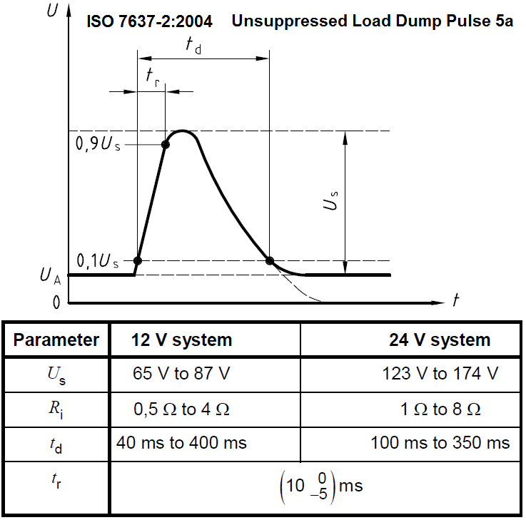
ime, you cannot have too much input protection!
Assuming your device has a correctly specified and protected power supply architecture (if the micro itself goes bang because some one has just jump started their car and placed the jump leads the wrong way around then it's a bit late to be worrying about input protection for any logical input etc!) then you need to try to include as much resistance as possible, commensurate with providing a sensible noise rejection. As most vehicles have a common ground (the body shell) galvanic isolation is rarely required (it can be useful in certain circumstances, for example interfacing to devices with high di/dt or high dv/dt)
For "simple" low frequency (<10khz) inputs i use a fixed resistive divider, followed by a voltage clamp (either diodes to Gnd / vcc, or a zener, depending on how near the rails i need the input signal to get), followed by more resistance, and then into the micro input pin. The second lot of R prevents excessive current flow through the micros internal clamping diodes and allows your out board clamps to shunt current away as necessary. I also add a select amount of capacitance to ground, a "small amount" directly on the input (needs a high enough voltage rating remember!) before the first resistive divider to provide a lower AC sink impedance (to try to shunt high frequency noise straight to ground) and then some more capacitance forming a low pass filter after the divider (frequency set to suit your input frequency range).
You also may consider using a series diode or zener to prevent reverse current flow if the vehicle battery is connected backwards and to push up the minimum input voltage which is considered to be "high" to give yourself some head room from ground potential.
-
As soon as a poster says "automotive" i know they are in a world of trouble!
firstly, automotive isn't "12v"!! Typical "normal" signal voltages range from as little a 8v (most oems now protect down to 6 to support cold cranking requirements) up to around 15v (14.7v is a typical alternator output setpoint)
However, abnormal events mean you need to be robust from -13vdc to around 90vdc (for 12v nominal systems)
ime, you cannot have too much input protection!
Assuming your device has a correctly specified and protected power supply architecture (if the micro itself goes bang because some one has just jump started their car and placed the jump leads the wrong way around then it's a bit late to be worrying about input protection for any logical input etc!) then you need to try to include as much resistance as possible, commensurate with providing a sensible noise rejection. As most vehicles have a common ground (the body shell) galvanic isolation is rarely required (it can be useful in certain circumstances, for example interfacing to devices with high di/dt or high dv/dt)
For "simple" low frequency (<10khz) inputs i use a fixed resistive divider, followed by a voltage clamp (either diodes to Gnd / vcc, or a zener, depending on how near the rails i need the input signal to get), followed by more resistance, and then into the micro input pin. The second lot of R prevents excessive current flow through the micros internal clamping diodes and allows your out board clamps to shunt current away as necessary. I also add a select amount of capacitance to ground, a "small amount" directly on the input (needs a high enough voltage rating remember!) before the first resistive divider to provide a lower AC sink impedance (to try to shunt high frequency noise straight to ground) and then some more capacitance forming a low pass filter after the divider (frequency set to suit your input frequency range).
You also may consider using a series diode or zener to prevent reverse current flow if the vehicle battery is connected backwards and to push up the minimum input voltage which is considered to be "high" to give yourself some head room from ground potential.
I should have mentioned in this case there's no alternator; the vehicle this is being designed for is not a standard street vehicle. It's my understanding that when the engine's not running the battery is isolated and when in the garage the battery is isolated and on charge.
Does the lack of alternator change the load dump by much or any of the protection requirements? (I imagine starting the vehicle would still cause a significant load dump when the starter is disengaged).
At the moment, the device is an Arduino Due + the shield I'm designing. I'm pushing for a single board (get rid of the Arduino and do a complete custom PCB) which would give me more control over the power supply and form factor - I'm not sure I'll get that though..
I've already added an unpopulated capacitor across the input to the microcontroller, would it be better off having it on the gate? or maybe even both?
I think I'd like to stick with the MOSFET inputs, but I'm wondering if maybe I should put a MOV or zener between the input resistor and the gate? VGS is +/- 20V continuous, so I'd only need to protect from transients above that. Would reverse current flow be an issue if there's a reverse polarity protection diode in the power supply (standard arduino) and a MOSFET on the input (no current from the gate?)
-
No alternator helps from "load being disconnected suddenly when it's sticking out 100A" type surges, but obviously makes no difference to any other (common) automotive environment surge!
Consider what does the additional mosfet bring you? You need to protect that Mosfets Gate, just like you need to protect the gate of the Mosfet (or similar device) in your microcontroller. In the event of a unprotectable surge (ie a surge that exceeds your protection system) that mosfet is dead, in the same way that the micro's input conditioning circuitry would be dead. End result is the same (there are some highly safety critical systems where you'd protect the micro at all costs because it's doing other stuff that is critical, but for your device, non functionality is non functionality is it not? Is there any other 'knock on' effect of possibly killing the micro itself?)
If you can present a valid reason for having an "active" input buffer, and considering that you don't have any requirement for low current consumption, or a requirement (particularly) high input impedance or bandwidth. i'd consider using a Transistor and not a Mosfet to get away from the Vgs limitation and obvious failure mode inherent in that semiconductors architecture.
But at just 1kHz, and with a (relatively speaking) massive input voltage range you can just install a huge series resistance into your input chain, and so effectively put in place a lot of over voltage protection easily. If you look up the voltage levels and hysteresis for your particular micro's input, you can easily work out a suitable voltage division and limitation mechanism to robustly protect that input.
ime, keeping things simple, but robustly engineered and validated is the trick for automotive electronics (and i design these for a living)
My principal "Five Commandments" are:
1) Power supply to the logic must be BULLETPROOF
2) Install the max impedance possible between the real world and your device, where ever signals cross the boundaries
3) Use the least possible number of parts. 1 less part = 1 less thing to fail
4) Protect ANY conductive path into your device from at least the following : 1) continuous connection to Vbatt+10% and continuous connection to -Vbatt
5) if you can achieve 4) for what ever reason, document that fact to your clients in an obvious and EXPLICIT way.
-
Quote from: max_torque on Yesterday at 11:20:37 PM
No alternator helps from "load being disconnected suddenly when it's sticking out 100A" type surges, but obviously makes no difference to any other (common) automotive environment surge!
Consider what does the additional mosfet bring you? You need to protect that Mosfets Gate, just like you need to protect the gate of the Mosfet (or similar device) in your microcontroller. In the event of a unprotectable surge (ie a surge that exceeds your protection system) that mosfet is dead, in the same way that the micro's input conditioning circuitry would be dead. End result is the same (there are some highly safety critical systems where you'd protect the micro at all costs because it's doing other stuff that is critical, but for your device, non functionality is non functionality is it not? Is there any other 'knock on' effect of possibly killing the micro itself?)
If you can present a valid reason for having an "active" input buffer, and considering that you don't have any requirement for low current consumption, or a requirement (particularly) high input impedance or bandwidth. i'd consider using a Transistor and not a Mosfet to get away from the Vgs limitation and obvious failure mode inherent in that semiconductors architecture.
But at just 1kHz, and with a (relatively speaking) massive input voltage range you can just install a huge series resistance into your input chain, and so effectively put in place a lot of over voltage protection easily. If you look up the voltage levels and hysteresis for your particular micro's input, you can easily work out a suitable voltage division and limitation mechanism to robustly protect that input.
ime, keeping things simple, but robustly engineered and validated is the trick for automotive electronics (and i design these for a living)
My principal "Five Commandments" are:
1) Power supply to the logic must be BULLETPROOF
2) Install the max impedance possible between the real world and your device, where ever signals cross the boundaries
3) Use the least possible number of parts. 1 less part = 1 less thing to fail
4) Protect ANY conductive path into your device from at least the following : 1) continuous connection to Vbatt+10% and continuous connection to -Vbatt
5) if you can achieve 4) for what ever reason, document that fact to your clients in an obvious and EXPLICIT way.
I was thinking the MOSFET would give me a high impedance input with negligible change in rise/fall time, a large input range as VGS(th) is small, and it would be easier to protect the MOSFET, as I only have to worry about transients >20V as opposed to the MCU that needs protecting from anything above 3.6V.
Having said all that, I posted in the beginner section because I don't know what I don't know and what I do know may be completely wrong.
From the MCU datasheet:
VIL: -0.3V min, 0.99V max (0.3 x VDDIO)
VIH: 2.31V min (0.7 x VDDIO), 3.6V max (VDDIO + 0.3)
Vhys: 150mV min, 500mV max
VIL leakage current: 5nA typ @ TA = 25°C, 30nA max @ TA = 85°C
VIH leakage current: 2nA typ @ TA = 25°C, 18nA max @ TA = 85°C
There's also an on-die series termination resistor of 36 ohms, but I think it can be ignored, as the ratings are at the pin, not after the resistor.
So where do I go from here for the calculation?
I tried following the example here: https://electronics.stackexchange.com/questions/124620/maximum-resistance-that-can-be-put-in-series-with-an-input-to-a-pic-microcontr
I assumed assuming TTL noise immunity of 400mV (but maybe I should be using 500mV or 150mV from the MCU's hysteresis?).
Max voltage across input resistor: 0.99V - 400mV = 0.59V
Max current: 30mA @85°
Max input resistor: 0.59V/30nA = 19.66 Mohms
...Which seems very large, and I'd imagine would cause issues...
So, would I take this (or perhaps a smaller value) and use that as the input resistor of a voltage divider and try to pick a ground resistor that would give VIH + 400mV for a Vin of 12V?
5V input
Min high input voltage = 2.31V + 400mV = 2.71V
R1: 10Mohms (<19.6Mohms)
R2: 12Mohm
Vout: 5*12/22 = 2.72V
12V input
Vout = 12 * 12/(22) = 6.54V
I would need a clamping diode for this scenario
Am I on the right track here?
-
Wow, there've been a lot of responses on this so I'll try to address them all - thanks guys!
That's a fairly low frequency, so the extra rise/fall time due to a resistor and get input capacitance won't matter.What frequency is the square wave?
The easiest method is to use a series resistor, say 10k to 1M, before the MCU input. The internal ESD protection diodes will clamp the input voltage at about 0.6V above the MCU's power supply.
Frequency will be around the 0-1kHz range, duty cycle of at least one signal is fixed at 20%, the others I don't know the duty cycle of (the requirements I've been given are not super detailed).QuoteFrom what I've read, the ESD diodes aren't designed for this kind of service and could be damaged/do degrade when used in this manner. I had considered a zener diode in parallel with the input or 2 Schottky diodes as others have suggested, however I'm concerned about loading the transducer (at least one post I've come across was complaining of loading issues even with 10s of kOhms of input resistance).
The ESD won't be damaged, so long as the current is limited to a safe value. A 100k resistor will limit the current to 87?A.Quote from: max_torque on Yesterday at 11:20:37 PM
How about using a potential divider and a clamping diode, such as the BAT54S, if you really want to avoid the ESD diode conducting, although it would be an issue at such low currents? Two 1M resistors would give the MCU, 2.5V with 5V in and it would be clamped to just over 3.3V, when the input voltage is above 6.6V. The current draw from the transducer will be negligible.No alternator helps from "load being disconnected suddenly when it's sticking out 100A" type surges, but obviously makes no difference to any other (common) automotive environment surge!
Consider what does the additional mosfet bring you? You need to protect that Mosfets Gate, just like you need to protect the gate of the Mosfet (or similar device) in your microcontroller. In the event of a unprotectable surge (ie a surge that exceeds your protection system) that mosfet is dead, in the same way that the micro's input conditioning circuitry would be dead. End result is the same (there are some highly safety critical systems where you'd protect the micro at all costs because it's doing other stuff that is critical, but for your device, non functionality is non functionality is it not? Is there any other 'knock on' effect of possibly killing the micro itself?)
If you can present a valid reason for having an "active" input buffer, and considering that you don't have any requirement for low current consumption, or a requirement (particularly) high input impedance or bandwidth. i'd consider using a Transistor and not a Mosfet to get away from the Vgs limitation and obvious failure mode inherent in that semiconductors architecture.
But at just 1kHz, and with a (relatively speaking) massive input voltage range you can just install a huge series resistance into your input chain, and so effectively put in place a lot of over voltage protection easily. If you look up the voltage levels and hysteresis for your particular micro's input, you can easily work out a suitable voltage division and limitation mechanism to robustly protect that input.
ime, keeping things simple, but robustly engineered and validated is the trick for automotive electronics (and i design these for a living)
My principal "Five Commandments" are:
1) Power supply to the logic must be BULLETPROOF
2) Install the max impedance possible between the real world and your device, where ever signals cross the boundaries
3) Use the least possible number of parts. 1 less part = 1 less thing to fail
4) Protect ANY conductive path into your device from at least the following : 1) continuous connection to Vbatt+10% and continuous connection to -Vbatt
5) if you can achieve 4) for what ever reason, document that fact to your clients in an obvious and EXPLICIT way.
I was thinking the MOSFET would give me a high impedance input with negligible change in rise/fall time, a large input range as VGS(th) is small, and it would be easier to protect the MOSFET, as I only have to worry about transients >20V as opposed to the MCU that needs protecting from anything above 3.6V.
Having said all that, I posted in the beginner section because I don't know what I don't know and what I do know may be completely wrong.
From the MCU datasheet:
VIL: -0.3V min, 0.99V max (0.3 x VDDIO)
VIH: 2.31V min (0.7 x VDDIO), 3.6V max (VDDIO + 0.3)
Vhys: 150mV min, 500mV max
VIL leakage current: 5nA typ @ TA = 25°C, 30nA max @ TA = 85°C
VIH leakage current: 2nA typ @ TA = 25°C, 18nA max @ TA = 85°C
There's also an on-die series termination resistor of 36 ohms, but I think it can be ignored, as the ratings are at the pin, not after the resistor.
So where do I go from here for the calculation?
I tried following the example here: https://electronics.stackexchange.com/questions/124620/maximum-resistance-that-can-be-put-in-series-with-an-input-to-a-pic-microcontr
I assumed assuming TTL noise immunity of 400mV (but maybe I should be using 500mV or 150mV from the MCU's hysteresis?).
Max voltage across input resistor: 0.99V - 400mV = 0.59V
Max current: 30mA @85°
Max input resistor: 0.59V/30nA = 19.66 Mohms
...Which seems very large, and I'd imagine would cause issues...
So, would I take this (or perhaps a smaller value) and use that as the input resistor of a voltage divider and try to pick a ground resistor that would give VIH + 400mV for a Vin of 12V?
5V input
Min high input voltage = 2.31V + 400mV = 2.71V
R1: 10Mohms (<19.6Mohms)
R2: 12Mohm
Vout: 5*12/22 = 2.72V
12V input
Vout = 12 * 12/(22) = 6.54V
I would need a clamping diode for this scenario
Am I on the right track here? -
That's a fairly low frequency, so the extra rise/fall time due to a resistor and get input capacitance won't matter.
The ESD won't be damaged, so long as the current is limited to a safe value. A 100k resistor will limit the current to 87?A.
How about using a potential divider and a clamping diode, such as the BAT54S, if you really want to avoid the ESD diode conducting, although it would be an issue at such low currents? Two 1M resistors would give the MCU, 2.5V with 5V in and it would be clamped to just over 3.3V, when the input voltage is above 6.6V. The current draw from the transducer will be negligible.
I've run a sim on the voltage divider with a zener diode for overvoltage protection (see attached).
It seems with a 1M/1M voltage divider, followed by a 1k resistor and a zener diode, with a pulse up to 87V, the most the MCU pin will see is 3.9V, then there's the internal 36R and the internal ESD diodes, would that be sufficient?
Looking at the BAT54S, where would you place it? Before the VDiv or after it?
If I understand the purpose correctly, if the signal is >=250mV above the rail, the diode will conduct and bleed the current into the 3.3V supply (hence the need for a "robust supply"?), resulting in the voltage dropping to a safe level.
Would I be better off using the BAT54S in place of the Zener? or perhaps in addition to the Zener (attachment 2)? Are other resistors etc. required (e.g. Vdiv->1k->schottkys->1k->zener->MCU)?
This article on digikey suggests a single Schottky, a low pass filter and a Zener for input protection and level shifting from 12V, however they are only worried about input line inductance over long distances, not load dump: https://www.digikey.com.au/en/articles/techzone/2012/apr/protecting-inputs-in-digital-electronics
Thanks for your help so far, max_torque & Hero999, I'm sure it's frustrating trying to explain this.
-
There is something wrong with your simulation. It would take well over 40000 volts to pump 39.5 ma through a 1 meg resistor and the zener diode.
In any case, 1 meg for the voltage divider resistors seems way too high.