Author Topic: #562 – Electroboom!  (Read 132784 times)

0 Members and 1 Guest are viewing this topic.

Offline Sredni

  • Frequent Contributor
  • **
  • Posts: 746
  • Country: aq
Re: #562 – Electroboom!
« Reply #675 on: December 08, 2021, 04:42:34 am »

The tiny batteries model, or: "You don't know the half of it"

"You keep using that word.
I don't think it means what you think it means.
"
 -- Inigo Montoya

Here is something that KVLers will find... unconceivable. (I will come back to this post for formatting and for adding the pictures in a couple of days)

Let's start from Faraday's law, in its modern integral form

    circulation of E = - d/dt flux of B

We already established that there is no particular place on the path where we can localize the inductive EMF represented by the surface integral on the right. Even if we split the circulation of E in the path integrals along several segments we can partition the path into, none of the segment can account for the inductive EMF on the right. If we bring the whole surface integral on the left hand side of the equation we get

    circulation of E + d/dt flux of B = 0

But this won't make E conservative.
There is, though, some mathematical trick we can pull to transform the surface integral of B into a line integral of something related to B and then incorporate this something into the integrand of the original path integral of E.

SPOILER ALERT GALORE:
What we will find is the circulation of something that is not E, but something else that has zero circulation and as such admits a scalar potential (which I will call phi to avoid any confusion with voltage).

Spoiler alert part I: it turns out that 'that something else' is the conservative part of the electric field E, a quantity that I will denote with Ecoul.

Spoiler alert part II: the electric field E can be seen as the composition of its conservative (irrotational) part Ecoul with its non-conservative (solenoidal) part Eind. This is the Helmoltz decomposition of a generic vector field and it holds under very general assumption (basically always):

    E = Ecoul + Eind

Moreover, to avoid confusion, I will also use the symbol Etot, instead of just E, to the denote the electric field.    

    Etot = Ecoul + Eind

But it has to be clear that Etot(x,y,z,t) (that is E(x,y,z,t) ) is the one and only electric field an electron, or any test charge, will experience at the point (x,y,z) at time t. Electrons do not have an accountant to tell them how much of the electric field they experience is due to the changing flux and how much to the displaced charge. The just react to the whole shebang.

We can start to massage our relation starting from the the vector potential A. Since div B = 0 we can express the magnetic field B as the curl of another vector field A:

    B = curl A

Our Faraday equation will become

    circulation of Etot + d/dt flux of curl A = 0

We can now use Stokes' theorem to turn the surface integral of the curl of A into the path integral of A along the boundary of the surface

    circulation of Etot + d/dt circulation of A = 0

If the ring is stationary we can bring the time derivative inside the integral

    circulation of Etot + circulation of dA/dt = 0

Now we can incorporate the second circulation integral into the first and we obtain the circulation of a field that is conservative

    circulation of (Etot + dA/dt) = 0

But notice what the integrand is: it is Ecoul, the conservartive PART of the total electric field

    Ecoul = Etot - Eind = Etot - (-dA/dt) = Etot + dA/dt

Ecoul has zero circulation and as such admits a potential function. This potential function is the scalar electric potential phi (some call it V, generating confusion) that obeys what we could call KsPDL (Kirchhoff's scalar Potential Difference Law).
It represents a partial description of the system because phi completely describes Ecoul, but only PARTIALLY describes Etot. In order to know Etot (the actual electric field felt by the charges) we need to know BOTH potentials: the electric scalar potential phi AND the magnetic vector potential A.

    Etot = - grad phi - dA/dt

Where does the tiny batteries model come from?
The tiny batteries model is not a model of the complete physical system "ring with resistors" described by Etot, but only a model of the effects of the partial, conservative part Ecoul alone. As a matter of fact, the tiny batteries represent the term associated with the negative of the induced field Eind = -dA/dt that we need to strip from Etot to get the conservative field Ecoul

    Ecoul = Etot - Eind = Etot - (-dA/dt)

This figure show the fields inside the conductor and the resistors of Lewin's ring for the case of zero-resistance wires.


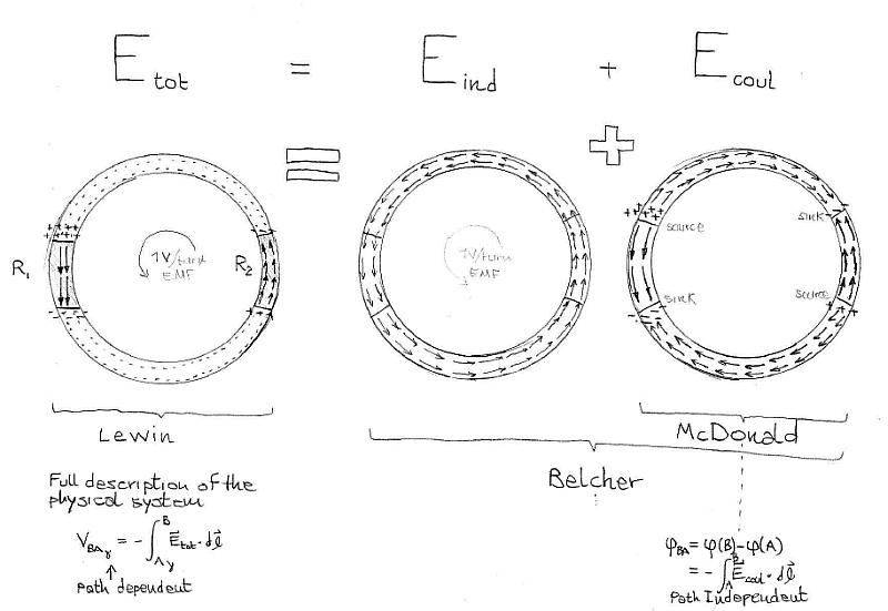
Only the ring on the right expresses a conservative field, and as such it can be represented by tiny lumped components obeying K"V"L (it's KsPDL, actually). I am using tiny batteries because it makes easier to see at first glance the polarity.It would be more accurate to use tiny generators, since in general the EMF contribute is time-varying, but if we freeze the system at a particular instant in time, we can pretend we are dealing with tiny batteries.

fig model with tiny batteries, no resistance in wires

The model can be generalized to the case of resistive wires. In practice we break the ring in tiny segments for which we have two contributes: the tiny resistor that represents the conductivity of the material and the tiny battery that represent the 'EMF eraser' that will recover Ecoul from Etot.

fig model with tiny batteries and resistors

This being the model of a mathematical part of the system, it will break the laws of physics obeyed by the actual, complete, system. Case in point: Ohm's law. Consider any portion of copper conductor and we will see that a piece of metal with a resistance that is almost zero will appear to drop a voltage (actually it's a scalar electric potential difference) of, say, 0.25 volts when a current of just 1 mA flows through it.

-buffering-

All instruments lie. Usually on the bench.
 
The following users thanked this post: emece67

Offline Jesse Gordon

  • Regular Contributor
  • *
  • Posts: 126
  • Country: us
Re: #562 – Electroboom!
« Reply #676 on: December 13, 2021, 01:21:12 am »
Regarding the "tiny voltage sources", the funny thing (which is a bit sad also) is that all the "experimental proof" by Jesse and e.g. Cyriel Mabilde are just cunning demonstrations of how to create paths that enclose a variable amount of magnetic flux. The sad part is that they're unable to see it and will keep claiming it is proof of "KVL holds". But in reality they're not measuring a gradual voltage build-up in the "Lewin Ring", but just the EMF induced in their measurement loop. This under the condition that there is only negligible current flowing through the ring and the measurement loop, of course.

The funny and sad thing is that you don't see that by measuring the voltage induced across a half of the dB/dt area we're actually unambiguously physically measuring the actual voltage induced in that half !

Think about it. Look at the circular area of dB/dt of my Lewin Clock. Now imagine we removed exactly half of that but maintained  D shaped aree at the other half with exactly the same dB/dt in that half as was there before. The dB/dt exactly the same.

Running the probe lead straight through the center of the circle does objectively unambiguously physically measure the voltage induced in that half of the winding.

And thus KVL holds my my Lewin Clock topology.
 

Offline Jesse Gordon

  • Regular Contributor
  • *
  • Posts: 126
  • Country: us
Re: #562 – Electroboom!
« Reply #677 on: December 13, 2021, 01:32:04 am »
For this 900 ohm resistor measurement, I had to be more careful not to pick up an induced voltage in the probing wires, so I used the setup shown in one of the attached pictures.

Cool! That's what I thought. Jesse measured the wrong voltage. He let his probes pick up induced voltage.

Nonsense. I practiced safe probing, and KVL works. Welcome to the real world kiddo  :-DD :-DD :-DD.
Quote
Thank you, jesuscf. We finally managed to show that Jesse's experiments are a hoax.
My experiment is not a hoax.  The reason you couldn't see my experiment in my garage is because you were in your mums basement at the time  :-DD :-DD :-DD.
Quote
No wonder he left the discussion. He knew he would be caught and exposed sooner or later by your imaginative intellect.
I didn't leave the discussion, unlike you, I don't live in my mom's basement so I have to work and I have friends and family to interact with so I can't be arguing on here every day.

I told you I'd limit my posting days to 2 days a week here. Since I was too busy last week that gives me 4 days here this week if I have time LOL.

Besides, I've already determined that you don't know what you're talking about by how you absolutely refused to answer the questions I asked. Sure, you would ask your own question and answer that, but you absolutely refused to actually exactly answer my question, which I will repeat for you below in case you forgot it.

Question: In the following diagram, in a real life physical lab test performed with real (time synchronized) volt meters with a real transformer and real resistors CONNECTED AS SHOWN, will the readings of all the volt meters sum to zero, within the accuracy and resolution limitations of the volt meters? YES or NO.

(Or if you believe SOMETIMES is the answer, then answer SOMETIMES and explain one scenario for a YES condition and one scenario for a NO condition WITH THE VOLT METERS AND ALL COMPONENTS CONNECTED AS SHOWN - Running additional conductors through the transformer core is not allowed - nor is removing existing conductors from through the transformer core!)


Offline Jesse Gordon

  • Regular Contributor
  • *
  • Posts: 126
  • Country: us
Re: #562 – Electroboom!
« Reply #678 on: December 13, 2021, 02:15:30 am »
Of course. The MIT is notoriously known for its scarcely prepared professors of physics and engineering.
Here is yet another professor who does not understand the basics of electromagnetism!
Shame on you, MIT!!!
Listen to the guys in a garage, instead. They have an oscilloscope, so they clearly know what they are talking about.

You know, right there is rock solid proof that you don't know what you're talking about.

Think about it. You keep going on about us "guys in their garages." That is like the purest form of argumentum ad hominem because being in a garage has absolutely nothing whatsoever to do with whether we are right or not.

The fact that you argue based on personal attacks regarding completely unrelated issues which have no bearing on whether we're right tells me that's all you got.

Since you brought up my garage, why don't you get a scope for your mom's basement and do some experiments? Your moms basement will be just as cool as my garage if you add a scope for sure.

You could even convert that 1980's CRT tv you got down there into a scope if you want..

Want digital storage? well how about analog storage? You can convert your VHS recorder to a waveform storage unit.

You already accidentally admitted to enough facts that you've really cornered yourself.

You gloriously cited this this textbook:

https://i.postimg.cc/sf4j3HbF/Desoer-Kuh.jpg

For ease of reading and searchability, I reproduce it here:

Quote from: Desoer-Kuh

Lumped circuits are obtained by connecting lumped elements. Typical
lumped elements are resistors, capacitors, inductors, and transformers.
We have encountered them in the laboratory, and we can see them in our
radio sets. The key property associated with lumped elements is their
small size (compared to the wavelength corresponding to their normal
frequency of operation.)  From the more general electromagnetic field point
of view, lumped elements are point singularities; that is, they have negligible
physical dimensions. In this way they are similar to a particle.
Lumped elements may have two terminals, as in a resistor, or more than
two terminals, as in a transformer or transistor. For two-terminal
lumped elements, it can be shown that the general laws governing the
electromagnetic field, together with the restriction on physical size indicated
above, imply that at all times the current entering one terminal is
equal to the current leaving the other terminal, and that the voltage difference
between the two terminals can be unambiguously defined by physical
measurements.  Thus, for two-terminal lumped elements, the current
through the element and the voltage across it are well-defined quantities. For
lumped elements with more than two terminals, the current entering any
terminal and the voltage across any pair of terminals are well defined at all times.

  For the remainder of this book, any interconnection of the lumped
elements such that the dimensions of the circuit are small compared with the
wavelength associated with the highest frequency of interest will be called
a lumped circuit.
  As long as this restriction on the size of the circuit holds, Kirchhoff's
current and voltage laws (to be discussed in Secs. 3 and 4) are valid. This
restriction is a consequence of the fact that Kirchhoff's laws are approximations
of Maxwell's celebrated equations, which are the general laws
of the electromagnetic field.  The approximation is analogous to the fact
that Newton's laws of classical mechanics are approximations to the laws
of relativistic mechanics.  Even though they are approximations, the laws
of Newton and Kirchhoff can be applied to a large number of practical


Clearly, the output voltage of my transformer secondaries in the diagram directly below are "unambiguously physically defined by physical
measurements" as described in the revered textbook cited directly above.


https://i.postimg.cc/jdJntBXT/20211128-121506.jpg

The fact that you won't even concede that KVL holds in this case shows you really don't know what's going on, you don't have a scope, and you've got less training on the topic than I do if that's even possible LOL.

KVL clearly holds (and should hold!) both on paper and in the garage!  :-DD :-DD :-DD

What else is there even to talk about?

Might as well pull up your crystal ball. BS has one you can borrow if you like, it kept shorting out on him so he had to get a new one. Thinkfat has one you can borrow a well, it's only been used once.


https://i.postimg.cc/5NsPHxQ4/3Gypsies.jpg
 

Offline bsfeechannelTopic starter

  • Super Contributor
  • ***
  • Posts: 1668
  • Country: 00
Re: #562 – Electroboom!
« Reply #679 on: December 13, 2021, 02:17:11 am »
Nonsense. I practiced safe probing, and KVL works. Welcome to the real world kiddo  :-DD :-DD :-DD.

"Safe probing" is for the weak. Real men measure the "interference".
 

Offline jesuscf

  • Frequent Contributor
  • **
  • Posts: 503
  • Country: ca
Re: #562 – Electroboom!
« Reply #680 on: December 13, 2021, 03:26:04 am »
Since this thread has sprung back to live, let me share some information to further demolish team's Lewin position.  Check out this marvelous quote from an old book:

Quote
Let the components of the electromotive intensity be X, Y, Z.
The electromotive intensity at any point is the resultant force on a unit of positive electricity placed at that point.  It may arise (1) from electrostatic action, in which case if V is the potential,
 \$X=-\frac{dV}{dx},Y=-\frac{dV}{dy},Z=-\frac{dV}{dz};    (1)\$
or (2) from electromagnetic induction, the laws of which we shall afterwards examine; or (3) from thermoelectric or electrochemical action at the point itself, tending to produce a current in a given direction.
We shall in general suppose that X, Y, Z represent the components of the actual electromotive intensity at the point, whatever be the origin of the force, but we shall occasionally examine the result of supposing it entirely due to variation of potential.

Where that quote comes from? From this book: A Treatise On Electricity and Magnetism by James Clerk Maxwell (page 418, Dover edition from 1954 based in third edition published in 1891)!  So, should we treat the EMF due to electromagnetic induction differently from the point of view of KVL to any other EMF?  I think Maxwell is telling us 'no' way back in time from 1873 when he wrote the book!  If you continue reading, the rest of the explanation looks pretty much like KVL and KCL to me, which he introduced earlier in the same book starting in page 406.


Homer: Kids, there's three ways to do things; the right way, the wrong way and the Max Power way!
Bart: Isn't that the wrong way?
Homer: Yeah, but faster!
 

Offline Jesse Gordon

  • Regular Contributor
  • *
  • Posts: 126
  • Country: us
Re: #562 – Electroboom!
« Reply #681 on: December 13, 2021, 03:39:41 am »
Nonsense. I practiced safe probing, and KVL works. Welcome to the real world kiddo  :-DD :-DD :-DD.
"Safe probing" is for the weak. Real men measure the "interference".

You know, you guys have shamed people for using scopes in their garages for a while now, I think it's high time you told us where you're doing your experiments. At least we're doing experiments. It's high time you tell us something about your degrees and experience.

You told us how you like to take calculators apart but that it's too noisy in your "lab" so you have to use a text to speech program for your video. "Wow, look at the amount of corrosion on those self tapping screws! Look what we have here, the leakage may have effected the tracks. ....  This is called multiplexing, so I read on Wikipedia. ... Now the calculator is restored to its glory! Good night and stay beautiful! "  (https://youtu.be/-qJebvO23Y8)

And here's you repairing a $20 kitchen scale: https://youtu.be/y3BRjA6jOyA

And here's you repairing a camera which you got from a dumpster: https://youtu.be/vhG3WvryEW0

And you fixing an old worn out electric drill motor: https://youtu.be/bDv9G7ezGss

Those are all super cool projects, but look. You and I have more in common than you think. You're just another guy like me who takes things apart and looks on wikipedia and does our best to figure out what's going on and definitely gets old junk out of dumpsters and from friends and fixes it up.

If either one of us had nice big fat degrees, we wouldn't be dumpster diving and fixing up common easily replaced household appliances. We probably wouldn't even be here arguing about this.

Hey, you used to have a scope: https://youtu.be/mT6FGdfeCNo?t=275

Again, just like me, we both have (or do you still have?) a cheapo scope. (Mine's Siglent which is another cheapo brand similar to your Regol.) (My vintage CRT analog scopes are Tek, but the DSO's are Siglent.)

If we were big degreed professionals, we'd have Tek/HP/Agilent/Keysight scopes.

But dood, we're both hobbiests. And that's a wonderful thing to be. Why not admit it?

The reason we do things in our garages is because that's what we have. Neither one of us pulls stuff from the dumpster then walks into our PHD level lab complex and goes into a clean room to fix whatever we pulled from the dumpster.

So what's your story? You were taking EE and dropped out? Was the scope yours, or did it belong to the school?

Why pass yourself off as something you're not? Who you really are is every bit as cool, and it's OK that there's things you don't understand -- goodness there's things I don't understand, like why you won't answer my question below about my transformer loop.

In cased you missed my question, I'd really appreciate you answering it.

Question: In the following diagram, in a real life physical lab test performed with real (time synchronized) volt meters with a real transformer and real resistors CONNECTED AS SHOWN, will the readings of all the volt meters sum to zero, within the accuracy and resolution limitations of the volt meters? YES or NO.

(Or if you believe SOMETIMES is the answer, then answer SOMETIMES and explain one scenario for a YES condition and one scenario for a NO condition WITH THE VOLT METERS AND ALL COMPONENTS CONNECTED AS SHOWN - Running additional conductors through the transformer core is not allowed - nor is removing existing conductors from through the transformer core!)


Offline Jesse Gordon

  • Regular Contributor
  • *
  • Posts: 126
  • Country: us
Re: #562 – Electroboom!
« Reply #682 on: December 13, 2021, 03:49:04 am »
For this 900 ohm resistor measurement, I had to be more careful not to pick up an induced voltage in the probing wires, so I used the setup shown in one of the attached pictures.

Cool! That's what I thought. Jesse measured the wrong voltage. He let his probes pick up induced voltage.

Thank you, jesuscf. We finally managed to show that Jesse's experiments are a hoax. No wonder he left the discussion. He knew he would be caught and exposed sooner or later by your imaginative intellect.

By the way, which  measurement are you saying was where I measured the wrong voltage? The iron-core or the Lewin Clock?
 

Offline Jesse Gordon

  • Regular Contributor
  • *
  • Posts: 126
  • Country: us
Re: #562 – Electroboom!
« Reply #683 on: December 13, 2021, 04:04:04 am »
If you don't trust what I said about the circuit equivalent of the resistors in the original one-loop ring, just build it, measure it, and post your results.

Look at the video posted by your fellow KVLer, fromjesse


He used big chunky 5W ceramic resistors, one is 150 Ω and the other is 47 Ω, 5% tolerance. The transformer is wound at about 200mV per turn, which gives you 1mA in the loop, and the voltages he measures are exactly what should be: around 150mV and 48 mV, respectively.

Man, I can't get enough of debunking your KVLer claims. And it's so easy since you KVLers provide all the evidence we need to.

And then in another post:

For this 900 ohm resistor measurement, I had to be more careful not to pick up an induced voltage in the probing wires, so I used the setup shown in one of the attached pictures.

Cool! That's what I thought. Jesse measured the wrong voltage. He let his probes pick up induced voltage.

Thank you, jesuscf. We finally managed to show that Jesse's experiments are a hoax. No wonder he left the discussion. He knew he would be caught and exposed sooner or later by your imaginative intellect.

What do you mean you finally managed to show what again? in other words, you've secretly believed it was a hoax this whole time, and now you think you got proof of it? If it was a hoax you could have demonstrated it in an instant with your scope.

But there was nothing hoaxical about my measurement. I used a real transformer and a real volt meter and measured exactly as I claimed and if you did the same thing you'd get the same results.

Are you seriously comparing my iron-core measurements to the open-pancake air core measurements?

You are clueless aren't you!
 

Offline Jesse Gordon

  • Regular Contributor
  • *
  • Posts: 126
  • Country: us
Re: #562 – Electroboom!
« Reply #684 on: December 13, 2021, 04:30:51 am »
Since this thread has sprung back to live, let me share some information to further demolish team's Lewin position.  Check out this marvelous quote from an old book:

Quote
Let the components of the electromotive intensity be X, Y, Z.
The electromotive intensity at any point is the resultant force on a unit of positive electricity placed at that point.  It may arise (1) from electrostatic action, in which case if V is the potential,
 \$X=-\frac{dV}{dx},Y=-\frac{dV}{dy},Z=-\frac{dV}{dz};    (1)\$
or (2) from electromagnetic induction, the laws of which we shall afterwards examine; or (3) from thermoelectric or electrochemical action at the point itself, tending to produce a current in a given direction.
We shall in general suppose that X, Y, Z represent the components of the actual electromotive intensity at the point, whatever be the origin of the force, but we shall occasionally examine the result of supposing it entirely due to variation of potential.

Where that quote comes from? From this book: A Treatise On Electricity and Magnetism by James Clerk Maxwell (page 418, Dover edition from 1954 based in third edition published in 1891)!  So, should we treat the EMF due to electromagnetic induction differently from the point of view of KVL to any other EMF?  I think Maxwell is telling us 'no' way back in time from 1873 when he wrote the book!  If you continue reading, the rest of the explanation looks pretty much like KVL and KCL to me, which he introduced earlier in the same book starting in page 406.

Indeed. And why wouldn't he? It makes sense. Doing otherwise makes no sense.

There's just no logical reason for Team Lewin to keep on going.

If an element is small compared to the wavelength, and the current going in one terminal equals the that going out the other, and the voltage can be physically unambiguously physically defined by measurement, then there's no reason KVL doesn't hold.

Btw, great job on the mini Lewin Ring setup!
 

Offline Sredni

  • Frequent Contributor
  • **
  • Posts: 746
  • Country: aq
Re: #562 – Electroboom!
« Reply #685 on: December 13, 2021, 06:36:00 am »
Ah, good, the "Treatise".
Are we going to bring back ether, as well?

And yes, the EMF due to induction is a very special kind of EMF.
All the other ones fall into the circulation integral.

And, Jesse, when I say "listen to the guys in a garage" I am not comparing them to me, but to the university professors who wrote books and papers where this problem was carefully analyzed.
Purcell, Morin, Roche, Ramo, Whinnery, VanDuzer, Romer, Rosser, Zahn, Haus, Melcher, Nicholson, Brandao Faria, ...
« Last Edit: December 13, 2021, 07:02:00 am by Sredni »
All instruments lie. Usually on the bench.
 

Offline jesuscf

  • Frequent Contributor
  • **
  • Posts: 503
  • Country: ca
Re: #562 – Electroboom!
« Reply #686 on: December 13, 2021, 06:51:02 am »
Ah, good, the "Treatise".
Are we going to bring back ether, as well?

And yes, the EMF due to induction is a very special kind of EMF.
All the other ones fall into the circulation integral.

And then you wonder why I say you are delusional!  Dude, it is Maxwell himself (from "Maxwell equations" nonetheless) saying that the inductive EMF is to be treated exactly the same as the other kinds of EMF!!!

Here is another historic reference for you to digest.  The attached image is from the paper Complex Quantities and their use in Electrical Engineering; Charles Proteus Steinmetz; Proceedings of the International Electrical Congress, Chicago, IL; AIEE Proceedings, 1893; pp.33-74.  Notice how the author is using KVL with induced EMFs.


Homer: Kids, there's three ways to do things; the right way, the wrong way and the Max Power way!
Bart: Isn't that the wrong way?
Homer: Yeah, but faster!
 

Offline Sredni

  • Frequent Contributor
  • **
  • Posts: 746
  • Country: aq
Re: #562 – Electroboom!
« Reply #687 on: December 13, 2021, 06:56:52 am »
You are still stuck at the difference between KVL and extended KVL?
Oh, dear.

Wanna see how I can treat induction EMF as any other EMF?
Simple, I localize it, just like with lumped circuits with inductors, transformers, motors...
You're still stuck there?

It's written on Hayt's book, the one you quoted three or four years ago.
All instruments lie. Usually on the bench.
 

Offline jesuscf

  • Frequent Contributor
  • **
  • Posts: 503
  • Country: ca
Re: #562 – Electroboom!
« Reply #688 on: December 13, 2021, 07:13:38 am »
You are still stuck at the difference between KVL and extended KVL?
Oh, dear.

Wanna see how I can treat induction EMF as any other EMF?
Simple, I localize it, just like with lumped circuits with inductors, transformers, motors...
You're still stuck there?

It's written on Hayt's book, the one you quoted three or four years ago.

Now it is official: according to Maxwell (the guy from "Maxwell equations") and Steinmetz (the guy from "phasor analysis") you don't know what you are talking about!

By the way, I think you didn't understand that Hayt was explaining the contribution of inductive EMFs to KVL using Faraday's law from an historic perspective.  I thought that was pretty clear from the text.
Homer: Kids, there's three ways to do things; the right way, the wrong way and the Max Power way!
Bart: Isn't that the wrong way?
Homer: Yeah, but faster!
 

Offline jesuscf

  • Frequent Contributor
  • **
  • Posts: 503
  • Country: ca
Re: #562 – Electroboom!
« Reply #689 on: December 13, 2021, 05:02:35 pm »
Ah, good, the "Treatise".
Are we going to bring back ether, as well?

And yes, the EMF due to induction is a very special kind of EMF.
All the other ones fall into the circulation integral.

And, Jesse, when I say "listen to the guys in a garage" I am not comparing them to me, but to the university professors who wrote books and papers where this problem was carefully analyzed.
Purcell, Morin, Roche, Ramo, Whinnery, VanDuzer, Romer, Rosser, Zahn, Haus, Melcher, Nicholson, Brandao Faria, ...

I see you edited you message.  Since I noticed that you just dump references without reading and/or understanding them, and that you also quite often just lie, allow me to check a couple of these references:

Electricity and Magnetism by Purcell E.M., Morin D.J:

They have Problem 7.4 similar to Lewin's problem.  No solution to the problem given!  The problem asks "What will each voltmeter read?" but it is not asking what is the voltage between nodes A and D!  I have the impression that the problem wants to point out that you have to be careful when you measure voltages and the instrument probes are under the effect of an external varying magnetic field...

Fields and Waves in Communication Electronics by Simon Ramo, John R. Whinnery, Theodore Van Duzer:

At the beginning of chapter 4 they say this: "Kirchhoff's two laws provide the basis for classical circuit theory.  We begin with the voltage law as a way of reviewing the basic element values of lumped-circuit theory.  The law states that for any closed loop of a circuit, the algebraic sum of voltages for the individual branches is zero... the basis for this is Faraday's law for a closed path, written as..."  And then, they proceed to use KVL with induced EMFs to solve a bunch of stuff.  How is that supposed to support your position?
Homer: Kids, there's three ways to do things; the right way, the wrong way and the Max Power way!
Bart: Isn't that the wrong way?
Homer: Yeah, but faster!
 

Offline jesuscf

  • Frequent Contributor
  • **
  • Posts: 503
  • Country: ca
Re: #562 – Electroboom!
« Reply #690 on: December 13, 2021, 05:33:29 pm »
Since this thread has sprung back to live, let me share some information to further demolish team's Lewin position.  Check out this marvelous quote from an old book:

Quote
Let the components of the electromotive intensity be X, Y, Z.
The electromotive intensity at any point is the resultant force on a unit of positive electricity placed at that point.  It may arise (1) from electrostatic action, in which case if V is the potential,
 \$X=-\frac{dV}{dx},Y=-\frac{dV}{dy},Z=-\frac{dV}{dz};    (1)\$
or (2) from electromagnetic induction, the laws of which we shall afterwards examine; or (3) from thermoelectric or electrochemical action at the point itself, tending to produce a current in a given direction.
We shall in general suppose that X, Y, Z represent the components of the actual electromotive intensity at the point, whatever be the origin of the force, but we shall occasionally examine the result of supposing it entirely due to variation of potential.

Where that quote comes from? From this book: A Treatise On Electricity and Magnetism by James Clerk Maxwell (page 418, Dover edition from 1954 based in third edition published in 1891)!  So, should we treat the EMF due to electromagnetic induction differently from the point of view of KVL to any other EMF?  I think Maxwell is telling us 'no' way back in time from 1873 when he wrote the book!  If you continue reading, the rest of the explanation looks pretty much like KVL and KCL to me, which he introduced earlier in the same book starting in page 406.

Indeed. And why wouldn't he? It makes sense. Doing otherwise makes no sense.

There's just no logical reason for Team Lewin to keep on going.

If an element is small compared to the wavelength, and the current going in one terminal equals the that going out the other, and the voltage can be physically unambiguously physically defined by measurement, then there's no reason KVL doesn't hold.

Btw, great job on the mini Lewin Ring setup!

Yes, most textbooks put emphasis in the fact that the circuit has to be much smaller when compared to the wavelength of the fields before using Kirchoff's laws... them proceed to explain transmission lines were the wavelengths are comparable to the size of the circuit!  How they solve the problem?  Easy, hash the equivalent circuit into lots of smaller pieces!  It may not be pretty or easy to solve, but it certainly works!  Thankfully in many cases the circuit under consideration is in an steady state regime, where we can again use simple lumped representations for very large parts of the circuit.

I am pretty happy with my ring setup.  For its simplicity, it works surprisingly well.  I have made lots of experiments already.  Lately, I have been adding capacitors to the ring circuit and using my fancy multimeters (BM869, DMM4050, and Fluke45) at home to measure the voltages, showing in each case that KVL works as expected (consistently, with less that 2% error).  At work I have easy access to dozens of HP34401A, DMM4040, and FLuke45 multimeters. I am pretty tempted to measure all the voltages at once using a stack of those... but that will have to wait until work slows down a bit.

Homer: Kids, there's three ways to do things; the right way, the wrong way and the Max Power way!
Bart: Isn't that the wrong way?
Homer: Yeah, but faster!
 

Offline Sredni

  • Frequent Contributor
  • **
  • Posts: 746
  • Country: aq
Re: #562 – Electroboom!
« Reply #691 on: December 13, 2021, 11:39:12 pm »
I see you edited you message. 
I try not to make an excessive number of posts.

Quote
Since I noticed that you just dump references without reading and/or understanding them, and that you also quite often just lie, allow me to check a couple of these references:

Electricity and Magnetism by Purcell E.M., Morin D.J:
They have Problem 7.4 similar to Lewin's problem.  No solution to the problem given!  The problem asks "What will each voltmeter read?" but it is not asking what is the voltage between nodes A and D!  I have the impression that the problem wants to point out that you have to be careful when you measure voltages and the instrument probes are under the effect of an external varying magnetic field...
page 358


A little excerpt (bold mine) which some have difficulty in understanding:

"...Kirchhoff Loop rule is no longer valid"

I wonder what that could mean... Why, oh why couldn't they be any clearer???
But let's see the solution of the problem on page 710 (again, bold mine)

"The moral of this problem is that if a setup contains changing flux, it makes no sense to talk about the voltage difference (that is, the value of −integral of E·ds) between two points. It is necessary to state the path over which −integral of E · ds is calculated."

Still of the opinion it does not support my position, which is that KVL is no longer valid and voltage depends on path?
 :palm:

Quote
Fields and Waves in Communication Electronics by Simon Ramo, John R. Whinnery, Theodore Van Duzer:

At the beginning of chapter 4 they say this: "Kirchhoff's two laws provide the basis for classical circuit theory.  We begin with the voltage law as a way of reviewing the basic element values of lumped-circuit theory.  The law states that for any closed loop of a circuit, the algebraic sum of voltages for the individual branches is zero... the basis for this is Faraday's law for a closed path, written as..."  And then, they proceed to use KVL with induced EMFs to solve a bunch of stuff.  How is that supposed to support your position?

I'll show you how. Page 174 of the third edition

"let us take a closed integral of electric field along the conductor of the coil, returning by the path across the terminals. Since the contribution along the part of the path which follows the conductor is zero, all the voltage appears ACROSS the terminals.

I'll translate this for you: voltage ALONG the filament of the coil = 0; voltage ACROSS the terminals = V not zero.
KVL cannot survive two values of voltage between the same two points. Unless you use a trick and pretend that there is only one voltage, that ACROSS the coil, and pretend its a potential difference.

Read page 179

"In the above we seem to be treating voltage as potential difference when we take voltage of a node with respect to the chosen reference, but note that this is only after the circuit is defined and we are only breaking up the integral of E.dl into its contributions over the various branches. As illustrated in the preceding section, we do have to define the path carefully whenever there are inductances or other elements with contribution to voltage from Faraday's law."

But hey, and this is related to the above, have you noticed that Jesse is repeatedly posting the same image of a circuit with a transformer, two outputs on a circuit with resistors and a lot of voltmeters? Suppose one turn around the core gives you an emf of 1V.
Can you place the values of your "path independent voltage" inside all those voltmeters? Because I have a hunch you cannot do it, using the voltage that according to you builds up in the coil.
I can easily do it using my definition of voltage, in accordance with Purcell, Ramo etc, Haus etc, Brandao Faria, Zahn, etc... but I wonder if you have any idea of what 'your voltage' (or the 'McDonald voltage', if you prefer to call it that way) is, in that context.
(Pretty sure Jesse doesn't know either, because I've asked and he refused to answer)


Edit: further clarifies what "voltage" I want you to place inside those voltmeters.
I will place the values of "my" path dependent voltage once either you or Jesse post your solution.
« Last Edit: December 14, 2021, 05:20:44 am by Sredni »
All instruments lie. Usually on the bench.
 

Offline jesuscf

  • Frequent Contributor
  • **
  • Posts: 503
  • Country: ca
Re: #562 – Electroboom!
« Reply #692 on: December 14, 2021, 12:31:29 am »
I see you edited you message. 
I try not to make an excessive number of posts.

Quote
Since I noticed that you just dump references without reading and/or understanding them, and that you also quite often just lie, allow me to check a couple of these references:

Electricity and Magnetism by Purcell E.M., Morin D.J:
They have Problem 7.4 similar to Lewin's problem.  No solution to the problem given!  The problem asks "What will each voltmeter read?" but it is not asking what is the voltage between nodes A and D!  I have the impression that the problem wants to point out that you have to be careful when you measure voltages and the instrument probes are under the effect of an external varying magnetic field...
page 358


A little excerpt (bold mine) which some have difficulty in understanding:

"...Kirchhoff Loop rule is no longer valid"

I wonder what that could mean... Why, oh why couldn't they be any clearer???
But let's see the solution of the problem on page 710 (again, bold mine)

"The moral of this problem is that if a setup contains changing flux, it makes no sense to talk about the voltage difference (that is, the value of −integral of E·ds) between two points. It is necessary to state the path over which −integral of E · ds is calculated."

Still of the opinion it does not support my position, which is that KVL is no longer valid and voltage depends on path?
 :palm:

Quote
Fields and Waves in Communication Electronics by Simon Ramo, John R. Whinnery, Theodore Van Duzer:

At the beginning of chapter 4 they say this: "Kirchhoff's two laws provide the basis for classical circuit theory.  We begin with the voltage law as a way of reviewing the basic element values of lumped-circuit theory.  The law states that for any closed loop of a circuit, the algebraic sum of voltages for the individual branches is zero... the basis for this is Faraday's law for a closed path, written as..."  And then, they proceed to use KVL with induced EMFs to solve a bunch of stuff.  How is that supposed to support your position?

I'll show you how. Page 174 of the third edition

"let us take a closed integral of electric field along the conductor of the coil, returning by the path across the terminals. Since the contribution along the part of the path which follows the conductor is zero, all the voltage appears ACROSS the terminals.

I'll translate this for you: voltage ALONG the filament of the coil = 0; voltage ACROSS the terminals = V not zero.
KVL cannot survive two values of voltage between the same two points. Unless you use a trick and pretend that there is only one voltage, that ACROSS the coil, and pretend its a potential difference.

Read page 179

"In the above we seem to be treating voltage as potential difference when we take voltage of a node with respect to the chosen reference, but note that this is only after the circuit is defined and we are only breaking up the integral of E.dl into its contributions over the various branches. As illustrated in the preceding section, we do have to define the path carefully whenever there are inductances or other elements with contribution to voltage from Faraday's law."

But hey, and this is related to the above, have you noticed that Jesse is repeatedly posting the same image of a circuit with a transformer, two outputs on a circuit with resistors and a lot of voltmeters? Suppose one turn around the core gives you an emf of 1V.
Can you place the values of your "path independent voltage" inside all those voltmeters? Because I have a hunch you cannot do it, using the voltage that according to you builds up in the coil.
I can easily do it using my definition of voltage, in accordance with Purcell, Ramo etc, Haus etc, Brandao Faria, Zahn, etc... but I wonder if you have any idea of what 'your voltage' (or the 'McDonald voltage', if you prefer to call it that way) is, in that context.
(Pretty sure Jesse doesn't know either, because I've asked and he refused to answer)


Edit: further clarifies what "voltage" I want you to place inside those voltmeters.
I will place the values of "my" path dependent voltage once either you or Jesse post your solution.

Once again Purcel, the same as Hayt, is progressing through the subject in a sequential historical way when he writes:

Quote
A consequence of Faraday’s law of induction is that Kirchhoff’s loop rule (which states that \$\int_{}^{}E.ds=0\$ around a closed path) is no longer valid in situations where there is a changing magnetic field. Faraday has taken us beyond the comfortable realm of conservative electric fields.

If we take that in a different context, it will directly contradict what Maxwell says:

Quote
Let the components of the electromotive intensity be X, Y, Z.
The electromotive intensity at any point is the resultant force on a unit of positive electricity placed at that point.  It may arise (1) from electrostatic action, in which case if V is the potential,
 \$X=-\frac{dV}{dx},Y=-\frac{dV}{dy},Z=-\frac{dV}{dz};    (1)\$
or (2) from electromagnetic induction, the laws of which we shall afterwards examine; or (3) from thermoelectric or electrochemical action at the point itself, tending to produce a current in a given direction.
We shall in general suppose that X, Y, Z represent the components of the actual electromotive intensity at the point, whatever be the origin of the force, but we shall occasionally examine the result of supposing it entirely due to variation of potential.

As for the second quote:

"let us take a closed integral of electric field along the conductor of the coil, returning by the path across the terminals. Since the contribution along the part of the path which follows the conductor is zero, all the voltage appears ACROSS the terminals."

That is ABSOLUTELY incorrect as the induced voltage is distributed through the conductor as many experiments have demonstrated.

EDIT: You may also want to check page 199 of Fields and Waves in Communication Electronics where they explicitly contradict the statement above by considering the effect of the electric field between the turns of the inductor!


« Last Edit: December 14, 2021, 04:54:35 am by jesuscf »
Homer: Kids, there's three ways to do things; the right way, the wrong way and the Max Power way!
Bart: Isn't that the wrong way?
Homer: Yeah, but faster!
 

Offline bsfeechannelTopic starter

  • Super Contributor
  • ***
  • Posts: 1668
  • Country: 00
Re: #562 – Electroboom!
« Reply #693 on: December 14, 2021, 01:31:24 am »
Since this thread has sprung back to live, let me share some information to further demolish team's Lewin position. 

Aaww, the cute little KVLey demolished the argument of the big bad Lewin-Newey. Poor Lewin-Newey.
 

Offline jesuscf

  • Frequent Contributor
  • **
  • Posts: 503
  • Country: ca
Re: #562 – Electroboom!
« Reply #694 on: December 14, 2021, 02:02:51 am »
Since this thread has sprung back to live, let me share some information to further demolish team's Lewin position. 

Aaww, the cute little KVLey demolished the argument of the big bad Lewin-Newey. Poor Lewin-Newey.

I see your brain has already melted down...
Homer: Kids, there's three ways to do things; the right way, the wrong way and the Max Power way!
Bart: Isn't that the wrong way?
Homer: Yeah, but faster!
 

Offline Sredni

  • Frequent Contributor
  • **
  • Posts: 746
  • Country: aq
Re: #562 – Electroboom!
« Reply #695 on: December 14, 2021, 05:41:24 am »
Once again Purcel, the same as Hayt, is progressing through the subject in a sequential historical way when he writes:

Quote
A consequence of Faraday’s law of induction is that Kirchhoff’s loop rule (which states that \$\int_{}^{}E.ds=0\$ around a closed path) is no longer valid in situations where there is a changing magnetic field. Faraday has taken us beyond the comfortable realm of conservative electric fields.

If we take that in a different context,


What different context???
The context is "in situations where there is a changing magnetic field".

Quote
it will directly contradict what Maxwell says:

Quote
Let the components of the electromotive intensity be X, Y, Z.
The electromotive intensity at any point is the resultant force on a unit of positive electricity placed at that point.  It may arise (1) from electrostatic action, in which case if V is the potential,
 \$X=-\frac{dV}{dx},Y=-\frac{dV}{dy},Z=-\frac{dV}{dz};    (1)\$
or (2) from electromagnetic induction, the laws of which we shall afterwards examine; or (3) from thermoelectric or electrochemical action at the point itself, tending to produce a current in a given direction.
We shall in general suppose that X, Y, Z represent the components of the actual electromotive intensity at the point, whatever be the origin of the force, but we shall occasionally examine the result of supposing it entirely due to variation of potential.

Apart from the fact that Maxwell is simply enumerating the EMF available at the time: electrochemical piles/electrostatic machines,  thermopiles and em induction (remember, if you consider localized sources you can apply what today we call "extended KVL") - what if it actually contradicted Maxwell?
Maxwell believed in the existence of the luminiferous ether. He was wrong.
What we today call "Maxwell's equations" is the result of the work of Heaviside, using the notation expressed in the treatise would be maddening. Expliciting all gradients, curls, divergences...
A lot of thing has changed since 1865.

Quote
As for the second quote:

"let us take a closed integral of electric field along the conductor of the coil, returning by the path across the terminals. Since the contribution along the part of the path which follows the conductor is zero, all the voltage appears ACROSS the terminals."

That is ABSOLUTELY incorrect as the induced voltage is distributed through the conductor as many experiments have demonstrated.

EDIT: You may also want to check page 199 of Fields and Waves in Communication Electronics where they explicitly contradict the statement above by considering the effect of the electric field between the turns of the inductor!

Sure, page 199 comes after page 198. Where the section "Circuit which are not small compared with wavelength" starts and we are considering "4.10 Distributed effects and retardation".

I am trying to hold back that pun.
« Last Edit: December 14, 2021, 05:43:23 am by Sredni »
All instruments lie. Usually on the bench.
 

Offline jesuscf

  • Frequent Contributor
  • **
  • Posts: 503
  • Country: ca
Re: #562 – Electroboom!
« Reply #696 on: December 14, 2021, 06:33:00 am »

Quote
Let the components of the electromotive intensity be X, Y, Z.
The electromotive intensity at any point is the resultant force on a unit of positive electricity placed at that point.  It may arise (1) from electrostatic action, in which case if V is the potential,
 \$X=-\frac{dV}{dx},Y=-\frac{dV}{dy},Z=-\frac{dV}{dz};    (1)\$
or (2) from electromagnetic induction, the laws of which we shall afterwards examine; or (3) from thermoelectric or electrochemical action at the point itself, tending to produce a current in a given direction.
We shall in general suppose that X, Y, Z represent the components of the actual electromotive intensity at the point, whatever be the origin of the force, but we shall occasionally examine the result of supposing it entirely due to variation of potential.

Apart from the fact that Maxwell is simply enumerating the EMF available at the time: electrochemical piles/electrostatic machines,  thermopiles and em induction (remember, if you consider localized sources you can apply what today we call "extended KVL") - what if it actually contradicted Maxwell?
Maxwell believed in the existence of the luminiferous ether. He was wrong.
What we today call "Maxwell's equations" is the result of the work of Heaviside, using the notation expressed in the treatise would be maddening. Expliciting all gradients, curls, divergences...
A lot of thing has changed since 1865.

But one thing that has not changed since the time of Maxwell is that KVL explicitly includes electromagnetic induction EMFs which are not to be treated differently from any other EMFs, "whatever be the origin of the force"!
Homer: Kids, there's three ways to do things; the right way, the wrong way and the Max Power way!
Bart: Isn't that the wrong way?
Homer: Yeah, but faster!
 

Offline bsfeechannelTopic starter

  • Super Contributor
  • ***
  • Posts: 1668
  • Country: 00
Re: #562 – Electroboom!
« Reply #697 on: December 14, 2021, 02:17:17 pm »

Quote
Let the components of the electromotive intensity be X, Y, Z.
The electromotive intensity at any point is the resultant force on a unit of positive electricity placed at that point.  It may arise (1) from electrostatic action, in which case if V is the potential,
 \$X=-\frac{dV}{dx},Y=-\frac{dV}{dy},Z=-\frac{dV}{dz};    (1)\$
or (2) from electromagnetic induction, the laws of which we shall afterwards examine; or (3) from thermoelectric or electrochemical action at the point itself, tending to produce a current in a given direction.
We shall in general suppose that X, Y, Z represent the components of the actual electromotive intensity at the point, whatever be the origin of the force, but we shall occasionally examine the result of supposing it entirely due to variation of potential.

Apart from the fact that Maxwell is simply enumerating the EMF available at the time: electrochemical piles/electrostatic machines,  thermopiles and em induction (remember, if you consider localized sources you can apply what today we call "extended KVL") - what if it actually contradicted Maxwell?
Maxwell believed in the existence of the luminiferous ether. He was wrong.
What we today call "Maxwell's equations" is the result of the work of Heaviside, using the notation expressed in the treatise would be maddening. Expliciting all gradients, curls, divergences...
A lot of thing has changed since 1865.

But one thing that has not changed since the time of Maxwell is that KVL explicitly includes electromagnetic induction EMFs which are not to be treated differently from any other EMFs, "whatever be the origin of the force"!

If the induced EMF is not in the path of the circuit, yes, you can include it in KVL. If not, KVL fails.
 

Offline jesuscf

  • Frequent Contributor
  • **
  • Posts: 503
  • Country: ca
Re: #562 – Electroboom!
« Reply #698 on: December 14, 2021, 04:03:04 pm »

Quote
Let the components of the electromotive intensity be X, Y, Z.
The electromotive intensity at any point is the resultant force on a unit of positive electricity placed at that point.  It may arise (1) from electrostatic action, in which case if V is the potential,
 \$X=-\frac{dV}{dx},Y=-\frac{dV}{dy},Z=-\frac{dV}{dz};    (1)\$
or (2) from electromagnetic induction, the laws of which we shall afterwards examine; or (3) from thermoelectric or electrochemical action at the point itself, tending to produce a current in a given direction.
We shall in general suppose that X, Y, Z represent the components of the actual electromotive intensity at the point, whatever be the origin of the force, but we shall occasionally examine the result of supposing it entirely due to variation of potential.

Apart from the fact that Maxwell is simply enumerating the EMF available at the time: electrochemical piles/electrostatic machines,  thermopiles and em induction (remember, if you consider localized sources you can apply what today we call "extended KVL") - what if it actually contradicted Maxwell?
Maxwell believed in the existence of the luminiferous ether. He was wrong.
What we today call "Maxwell's equations" is the result of the work of Heaviside, using the notation expressed in the treatise would be maddening. Expliciting all gradients, curls, divergences...
A lot of thing has changed since 1865.

But one thing that has not changed since the time of Maxwell is that KVL explicitly includes electromagnetic induction EMFs which are not to be treated differently from any other EMFs, "whatever be the origin of the force"!

If the induced EMF is not in the path of the circuit, yes, you can include it in KVL. If not, KVL fails.

You don't even now what is KVL!
Homer: Kids, there's three ways to do things; the right way, the wrong way and the Max Power way!
Bart: Isn't that the wrong way?
Homer: Yeah, but faster!
 

Offline bsfeechannelTopic starter

  • Super Contributor
  • ***
  • Posts: 1668
  • Country: 00
Re: #562 – Electroboom!
« Reply #699 on: December 14, 2021, 05:07:54 pm »
You don't even now what is KVL!

KVL is a special case of Faraday's law when you don't have a time-varying magnetic field in the surface enclosed by the path of the circuit.


Share me

Digg  Facebook  SlashDot  Delicious  Technorati  Twitter  Google  Yahoo
Smf