Author Topic: HP 3314A function generator teardown / explanation  (Read 7302 times)

0 Members and 1 Guest are viewing this topic.

Offline D StraneyTopic starter

  • Regular Contributor
  • *
  • Posts: 189
  • Country: us
HP 3314A function generator teardown / explanation
« on: August 31, 2019, 03:11:10 am »
Was doing some troubleshooting on an old (late 80's, I think?) HP 3314A function generator at work not long ago, and as the insides were a good combo of interesting and aesthetically pretty nice, I took a few minutes to snap some photos while I was in there.  Still plenty useful even by modern standards, as it goes up to 20 Mhz and can do sweeps, digital control, etc.  Of course, more modern ones can do the same thing more easily, for less but it was interesting comparing the internals.

Here's the front panel:

...and here's a side view of the inside, after removing the separate top and bottom covers:

Notice that there's 3 boards in there, stacked vertically, with some flex cables (and one ribbon cable) running between them.

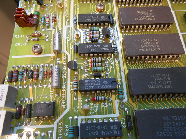
Starting at the top side, here's the top board:

Nothing super special here.  There's a 6800 processor and some memory/misc. digital stuff, a "system clock generator" with a crystal oscillator (this is what generates the reference clock for everything), a "reference amplifier" section (reference voltage generator for the system), and a string of power supplies, starting with the rectified transformer outputs at top-left and wrapping around through a few regulators on the bottom edge.

Interestingly enough, it has an SMPS (almost definitely a buck converter) for the +5V supply, from when they were still underground and cool:

Guess there must've been a lot of current draw from all the digital (we'll see more later too).  The mounting of the power transistor is interesting, as it's bolted to the sheet metal underneath, and its pins stick up through holes in the board into a connector mounted on the top side - this way you can remove the board without having to remove the power transistor (same goes for the +/- 15V regulators too) and re-do all the thermal grease / correct torque / etc.  Nice design for easy maintenance.

Here's one last scenic shot of those gold traces:


Speaking of easy maintenance...woah, are those hinges there?

Yep!  The whole top board and its mounting plate (which serves as the heatsink for its power supplies) just lifts up to expose the middle board.  I'm impressed.

I want this type of construction in everything I have to open up.

So next, you can see the middle board, which has a lot more going on than the top board, judging by the sections which are nicely labeled on the silkscreen:

This is where the circuitry starts to get interesting.
- So the modern function generators I took apart a few months back, as you would expect, go all in on DDS, mostly digital up until the end: with fast digital logic and fast precise DACs now being cheap and easily available, it makes the most sense by far to just synthesize a waveform entirely with a processor or FPGA, then stick it into a DAC and have a limited amount of analog filtering/scaling afterwards.  Besides better stability over temperature/age, you can do all sorts of fancy shit like waveforms made out of arbitrary points.
- At the other extreme, much older (50's - 70's) function generators were all analog, based on either a sinewave oscillator of some kind or the classic integrator-into-hysteretic-comparator triangle/square wave circuit:

...as DACs were either pretty low-performance or were the kind of things that got sent on space missions.
- Anyways, somewhere in between is this function generator.  They clearly wanted the features and accuracy that come with digital control, but were still limited by the DACs and digital logic available.  Having the sinewave frequency range extend up to 20 Mhz means needing a 40 Msps DAC at a bare minimum (and that would either make 19.9 Mhz impossible or require a fast-rolloff multi-pole filter with a voltage-controlled corner frequency), which wasn't feasible for this kind of thing until much later.  So, as I found out from the service manual's "theory of operation" section, the 3314A makes an interesting compromise: it's an analog core with crazy-HP-style digital controls and corrections wrapped around it.  For all the complexity you can see on this board and the next one as well, it all runs off a VCO based on the simple analog triangle wave generator circuit, same as in some cheap bullshit ICL8038 or whatever.
However, it has a calibration DAC output which trims both the positive and negative currents that get fed into the integrator, and therefore can correct both the frequency and waveform symmetry.  When you turn it on for the first time or change frequency ranges, it actually goes through a software calibration procedure to correct the frequency.  A PLL frequency synthesizer (fed from that reference crystal oscillator on the top board) generates a reference frequency at one end of the new range(?) and compares that with the analog VCO's output.  Depending on whether the VCO's frequency is too high or low, it then feeds in correction values from the trim DAC and re-checks the frequency until it's spot-on.  When in the 1 Mhz and 10 Mhz ranges, instead of a one-off calibration it actually keeps the analog VCO in the frequency-correction loop constantly, for stability I guess.  There's a whole amplitude calibration loop as well, but I didn't get into that since it seemed to be working fine.

They even managed to do arbitrary waveform generation with this partly-analog function generator, in an interesting way.  As opposed to a DDS-based function generator, where the arbitrary waveforms are inherently made out of "staircase" steps because of the DAC, here the VCO is based on an integrator, so the arbitrary waveforms it supports are made out of ramps.  The DAC feeds currents into the integrator, and each point in the arbitrary waveform is basically "feed this amount of current into the integrator for this amount of time".  Of course with a fast-enough ramp you can approximate a step, just like how with fine-enough steps you can approximate a ramp.

All the frequency synthesizer and calibration magic goes on on this middle board, and between the labeled sections in the photo above, and the service manual, you can get a decent idea of what's going on.  Sights include a re-branded Analog Devices DAC:

...and some disturbingly large power resistors:


Let's take a look on the bottom now, which has the analog stuff:

There's some mystery stuff in the top-right corner:

...the output amplifier, on its own separate board:

This has a pair of RF transistors:

...along with some gain-switching relays:

There's also some diodes with ferrite beads on their leads, next to each transistor:

...and what looks like a gas discharge tube near the output (maybe for protection against someone connecting an RF amp to the output connector?):


Like the top processor board, the output amp board is also mounted on a hinged plate, and lifts up to show a pre-amp section underneath:


Anyways, back to the rest of the bottom board, we can take off that metal can and see the VCO underneath:


There's a lot going on (seriously, read the service manual, it's got a pretty interesting tour of design decisions at the component level from what I remember), but there's some obvious things to pick out.  For example, the relays which switch ranges by selecting different capacitors (the round film ones, gotta have good stability and low leakage here) for the integrator circuit:

The highest frequency range has a trimmer capacitor used for calibration:

Its value then gets swamped out by the other cap values as they get added in on the lower ranges.

Oh and it's really easy to miss, there's a weird hybrid heatsinked to the underside of the shield:

When the shield's in place, it gets held against these spring pins on the board:

This hybrid is what does some signal shaping to create a sinewave from the "natural" triangle wave output of the VCO.  It's not described in the manual (which specifically says "you don't need to know, now move along") but I'd guess it has a huge ladder of precisely-trimmed resistors to vary the gain in piecewise steps (like the (shitty) way it's implemented in the ICL8038, but x100 as the output is way nicer), plus maybe some matched transistors for getting a non-linear response and smoothing in between those steps.  However it works, it seems to do a good job, not surprising I guess considering the effort put into each lowly transistor in the VCO circuit.

Anyways, that's it for the workings but there's more electronics porn in the full set of photos.
 
The following users thanked this post: MarkL, rodpp, NF6X, SilverSolder, bitseeker, genghisnico13, ch_scr, happy_mosfet, Rob2

Offline David Hess

  • Super Contributor
  • ***
  • Posts: 16641
  • Country: us
  • DavidH
Re: HP 3314A function generator teardown / explanation
« Reply #1 on: August 31, 2019, 04:27:31 am »
Test instruments from that age are real works of art.  I considered picking up an HP 3314A when I was looking for something but decided it was too complex to reliably maintain despite service documentation.

This hybrid is what does some signal shaping to create a sinewave from the "natural" triangle wave output of the VCO.  It's not described in the manual (which specifically says "you don't need to know, now move along") but I'd guess it has a huge ladder of precisely-trimmed resistors to vary the gain in piecewise steps (like the (shitty) way it's implemented in the ICL8038, but x100 as the output is way nicer), plus maybe some matched transistors for getting a non-linear response and smoothing in between those steps.  However it works, it seems to do a good job, not surprising I guess considering the effort put into each lowly transistor in the VCO circuit.

Distortion is about 0.2% at low frequencies so not any better than the best contemporary function generators which used similar techniques and fewer break points than the ICL8038.  From the look of the schematic, a translinear circuit with 3 Gilbert cells is used for sine shaping.

The ICL8038 uses 8 breakpoints for a rather uninspiring 1% distortion.  Old function generators using discrete circuits were typically much better than that.  I do not think anybody has ever accused integrated sine shapers of being high performance.  I suspect they suffer from the poor resistor tolerance available on older processes and there was never enough demand to make a good one.
 

Offline syau

  • Frequent Contributor
  • **
  • Posts: 368
  • Country: hk
Re: HP 3314A function generator teardown / explanation
« Reply #2 on: August 31, 2019, 09:56:07 am »
Wonder how did it compare with 8116A ?
 

Offline MarkL

  • Supporter
  • ****
  • Posts: 2134
  • Country: us
Re: HP 3314A function generator teardown / explanation
« Reply #3 on: August 31, 2019, 01:49:06 pm »
D Straney - thanks for the nice teardown photos!  I don't think I've ever seen RCA connectors inside HP test gear before.

Wonder how did it compare with 8116A ?
The 3114A and 8116A are from the same era but the 3114A is a much more sophisticated device with vector arb capability.  The 3114A also has phase lock input, better distortion characteristics, better flatness, and precise frequency control due to its phase lock design.

The 8116A is basically an analog generator with a microcontroller instead of knobs.  It has a lot of drift and inaccuracy in frequency.  On the plus side, it's smaller, has a max frequency of 50MHz vs. 20MHz, an output of 16Vpp vs. 10Vpp, slightly faster rise time of 7ns, and pulse width modulation.


If you want to read further, the specifications for both can be found in the 1987 HP catalog:

  http://hparchive.com/Catalogs/HP-Catalog-1987.pdf

And even more details for both are still available at keysight.com, including service manuals.

EDIT: Brain dropped a bit.  Obviously I meant 3314A in the above.
« Last Edit: August 31, 2019, 10:14:07 pm by MarkL »
 
The following users thanked this post: syau

Offline D StraneyTopic starter

  • Regular Contributor
  • *
  • Posts: 189
  • Country: us
Re: HP 3314A function generator teardown / explanation
« Reply #4 on: August 31, 2019, 04:49:11 pm »
Distortion is about 0.2% at low frequencies so not any better than the best contemporary function generators which used similar techniques and fewer break points than the ICL8038.  From the look of the schematic, a translinear circuit with 3 Gilbert cells is used for sine shaping.

The ICL8038 uses 8 breakpoints for a rather uninspiring 1% distortion.  Old function generators using discrete circuits were typically much better than that.  I do not think anybody has ever accused integrated sine shapers of being high performance.  I suspect they suffer from the poor resistor tolerance available on older processes and there was never enough demand to make a good one.

Interesting, I'll have to take a closer look at the connections going to the hybrid.  I'm probably being unfairly harsh on the resistor-diode-ladder method; my one real experience with it in practice was wiring up an ICL8038 not long ago to get a quick sinewave generator for some guitar effects circuits I was designing - even adding (and tweaking) all the recommended trimpots for symmetry, etc. the resulting waveform was horribly distorted even just "by inspection" on the scope (way worse than 1%).  To be fair though, that chip had been sitting around in my parts stash for over a decade so something could've happened to it along the way (or might've been defective in the first place).

Offline rf-loop

  • Super Contributor
  • ***
  • Posts: 4107
  • Country: fi
  • Born in Finland with DLL21 in hand
Re: HP 3314A function generator teardown / explanation
« Reply #5 on: August 31, 2019, 08:48:40 pm »
You can also listen it:

https://www.davmar.org/hp3314a.html

If yours is broken... listen it here
https://youtu.be/H90d6sPUF6A

Quote
Arbitrary Waveforms
For specialized low frequency applications, the 3314A's Arbitrary
(ARB) waveform mode lets you create custom waveforms as a series
of voltage ramps or vectors. Values are easy to enter from the front
panel using the modify knob as a "pencil" and an oscilloscope as a
"pad". For remote programming, use a desktop or mainframe computer
to calculate the values, then program them using the HP-IB.
Arb waveforms are automatically stored in non-volatile memory for
quick recall
« Last Edit: August 31, 2019, 08:53:11 pm by rf-loop »
I drive a LEC (low el. consumption) BEV car. Smoke exhaust pipes - go to museum. In Finland quite all electric power is made using nuclear, wind, solar and water.

Wises must compel the mad barbarians to stop their crimes against humanity. Where have the wises gone?
 
The following users thanked this post: Rob2

Offline SilverSolder

  • Super Contributor
  • ***
  • Posts: 6126
  • Country: 00
Re: HP 3314A function generator teardown / explanation
« Reply #6 on: September 01, 2019, 12:49:27 am »
It is amazing what's possible with even older analogue instruments!

https://youtu.be/WL9ZBNJs-Ss
 

Offline David Hess

  • Super Contributor
  • ***
  • Posts: 16641
  • Country: us
  • DavidH
Re: HP 3314A function generator teardown / explanation
« Reply #7 on: September 01, 2019, 01:32:17 am »
Distortion is about 0.2% at low frequencies so not any better than the best contemporary function generators which used similar techniques and fewer break points than the ICL8038.  From the look of the schematic, a translinear circuit with 3 Gilbert cells is used for sine shaping.

The ICL8038 uses 8 breakpoints for a rather uninspiring 1% distortion.  Old function generators using discrete circuits were typically much better than that.  I do not think anybody has ever accused integrated sine shapers of being high performance.  I suspect they suffer from the poor resistor tolerance available on older processes and there was never enough demand to make a good one.

Interesting, I'll have to take a closer look at the connections going to the hybrid.  I'm probably being unfairly harsh on the resistor-diode-ladder method; my one real experience with it in practice was wiring up an ICL8038 not long ago to get a quick sinewave generator for some guitar effects circuits I was designing - even adding (and tweaking) all the recommended trimpots for symmetry, etc. the resulting waveform was horribly distorted even just "by inspection" on the scope (way worse than 1%).  To be fair though, that chip had been sitting around in my parts stash for over a decade so something could've happened to it along the way (or might've been defective in the first place).

Check out the Tektronix FG5xx series of function generators which use a variety of sine shaper configurations and are fully documented.  The FG503 uses what might be considered traditional diode breakpoints, the faster FG502 and FG504 use diode bridges, and the slower but lower distortion FG501 and FG501A use differential pairs in a way that I suspect is very similar to the HP 3314A.  National Semiconductor published an application note discussing sine shaping using differential pairs but I do not remember how much detail it had.
 

Offline andymok

  • Contributor
  • Posts: 15
  • Country: hk
Re: HP 3314A function generator teardown / explanation
« Reply #8 on: January 08, 2022, 04:19:27 am »
Hello, thank you very much for the tear down!!

I have just received one in very good condition except, the transformer fried with the cooked capacitors.  I'm considering to order a new transformer to replace with, just to confirm, do you know the output voltage of the transformer?

Much appreciated.
« Last Edit: January 08, 2022, 04:21:24 am by andymok »
 

Offline D StraneyTopic starter

  • Regular Contributor
  • *
  • Posts: 189
  • Country: us
Re: HP 3314A function generator teardown / explanation
« Reply #9 on: January 09, 2022, 01:47:42 am »
The service manual schematic shows a center-tapped secondary with +/- 24V peak-charged on each side, so that should be about 18VAC on each side of the secondary (36VAC total), although it does get immediately regulated down to +/- 15V.  Judging from the over-current resistors, the foldback threshold on each rail is something like 1.3A.

Good luck with the repair.

Offline andymok

  • Contributor
  • Posts: 15
  • Country: hk
Re: HP 3314A function generator teardown / explanation
« Reply #10 on: January 10, 2022, 07:09:11 am »
Thank you very much Straney, for the valuable info.  Wish me luck.
 

Offline andymok

  • Contributor
  • Posts: 15
  • Country: hk
Re: HP 3314A function generator teardown / explanation
« Reply #11 on: January 18, 2022, 06:18:10 pm »
A little update.

Turns out the 3330uF input cap shorted out, causing everything in the path boiling hot.  Luckily the positive rail diodes are metal-canned, and while the transformer boiled it actually survived and didn't fail. 

On closer look, the transformer actually outputs 24-0-24, and rectified into ~32VDC, really close to the original 35V cap rating.

Anyways I have successfully powered it up now.  But there's still something wrong down the stream after J3 ......


Share me

Digg  Facebook  SlashDot  Delicious  Technorati  Twitter  Google  Yahoo
Smf