I picked up a Keithley 2000 on fleaBay, advertised as "Measures DC voltage properly, does NOT measure resistance at all." for about $200 shipped to my door. I didn't take any before photos, but thought some repair shots might be of interest. I was about to come here for help fixing it...when I fixed it...so posting a repair log.
On arrival, I expected to find things worse than described, as you'd expect. Surprisingly, that was not exactly the case. The meter was in externally "fair" shape, nothing appeared missing or broken except for the bail and feet which is pretty typical (and I assume not economical to replace). As described, however, none of the resistance ranges worked properly. Volts and amps on the ranges I am able to test appeared to work properly and in spec. I opened it up and had a peek around, hoping for a bad tantalum or obviously burnt components, but none were to be found. Everything looked fine. Boo.
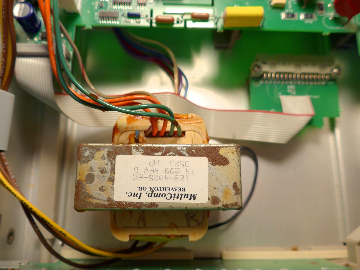
This was the worst of it - some rust on the power trafo:
Self tests passed except for 302.1 and 302.2, which failed initially. The symptom is that intermittently, the meter drifts all over the place, even goes negative, when in any ohms range. It doesn't seem to matter which range it's in, and the range doesn't seem to affect the drift rate. Other times it works perfectly for a while, then starts drifting. Maybe it will come back after switching modes or ranges, maybe not.
So first we'll test that the current source and its switching is working, since it's easy to test and an obvious ohms-only problem source:
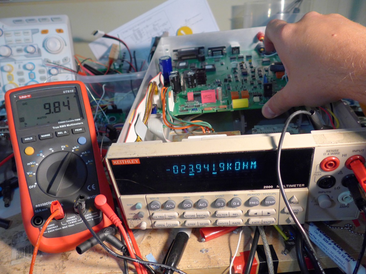
Looks good in all ranges, even while spamming garbage readings. I guess that means it's time to start tracing the input sense and see where we're losing it (at this point I should have realized it must be after the Isource is joined with INPUT). The first time through, I traced the signal in the schematic incorrectly and was on the wrong side of the board. Oops. After not much work, I found the signal wasn't getting past the string of 4x24k input resistors. I'd also noticed probing around that flexing the board would bring it into line or cause it to misbehave, so I knew now I was probably looking for a bad joint, cracked part or trace. This was a bit tricky to measure directly, since the 10M input impedance of the other meter I was using would drag the voltage to 0V and reading to 0R almost instantly. Of course, that was until I noticed it! Of course if it is able to drag it to 0 ohms I'm still on the opened side, no need to lean over to the bench meter. A minute or so of poking and aha! Here's the bastard that was acting up; this part of the board is subject to more flex than I'd like:
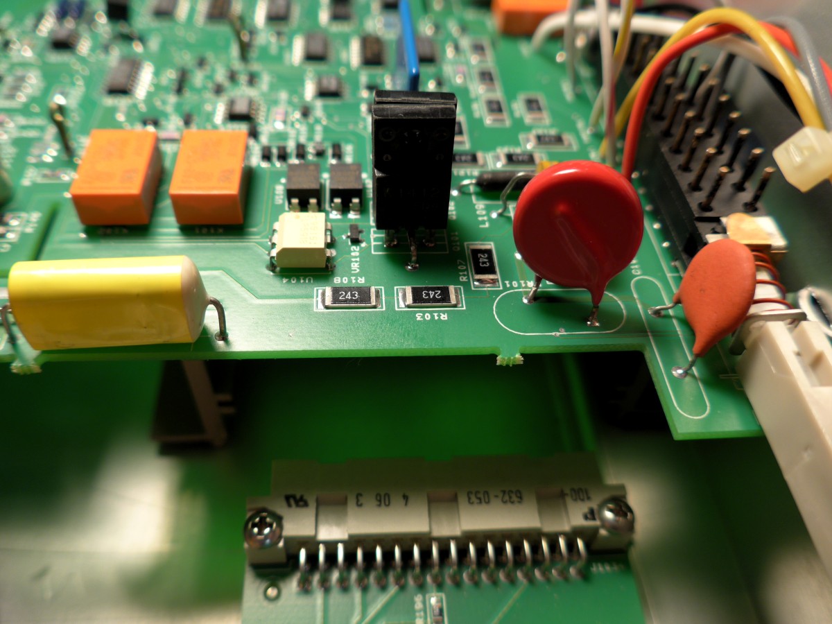
R108, you naughty devil.
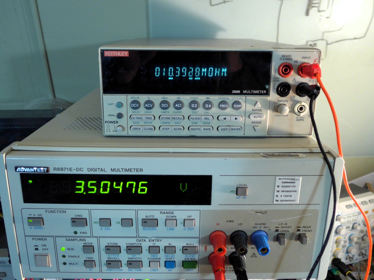
A quick reflow of the string of resistors and everything seems to be perfect now:
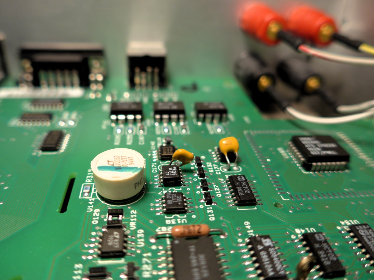
And of course, any opening of a precision instrument requires a moneyshot of its reference circuit!
(A few more random pics here if anyone is interested:
http://gotroot.ca/media/keithley_2000/ )
Now seems to be fully operational. Thanks to TiN for hosting the 38hot reverse engineered schematics (found
here), which made tracing the input a little easier. Thanks also to zucca for
found by zucca on his 34401A]fixing almost the identical problem with his 34401A the other day on the forum and lodging in my memory that I should check for broken joints.
I'm not sure if this thing has ever been calibrated. The rear screws said "warranty void if removed," nothing about calibration. Seems reasonably accurate though, agrees with my Advantest R6871E within 200uV and with my DMMCheck within 100uV. Now that R is fixed, it's basically bang on the DMMCheck measured values (I too) and matches my other "standards" on the ranges I am able to test.
PS. Any suggestions on cleaning the front/rear switch? It is quite sticky, the spring is not strong enough to fully return it.