Hi all,
Since DC load topics are often pop up here and there on EEVBlog, let me add some into mixture as well.
I hope fellow volt-nuts would not judge this one too hard, but I decided to open my old ATE design, which I did in 2008 or so. There is no precision better than 1% in this one here

, but it have 2000W of capacity!

Back then I had part-time job as reviewer on few PC websites, covering PC PSU evaluation and testing. All I had was a cheapie DMM and Tektronix 2246, which is not enough to do proper power supply testing, so I ended up with need of multichannel high-power DC load very quickly. Quick evaluation of market shown that I had no way in hell to get any of those multichannel beasts from Chroma and such with regular student money. Solution? If you can't buy it, make it!
Version 1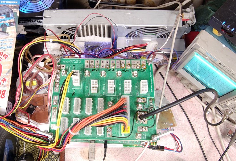
Hence the prototype was born, using MOSFET, CPU fansink, and bunch of opamps. I was into learning MCUs and programming them same time, so it was obvious to mix both together and make automatic DC loader/PSU tester. Bunch of MOSFETs in progress were burnt, of course

It ended up using IR FB180SA10P ISOTOP-package mosfets (really nice beasts, but expensive), ATMEL ARM7 MCU and multichannel 8bit DAC. No precision stuff, I barely knew anything about analog back then (not that I know a lot now either!

).
That thing worked, but was not so easy to use, as often some wires were getting loose, or some other bugs haunted it.
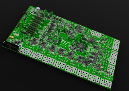
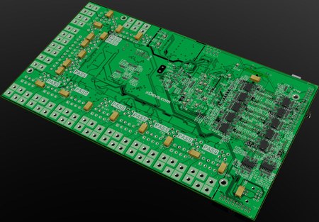
 Version 2
So I redesigned whole thing, and called it Neutron, as it was second iteration (first one was Proton

).
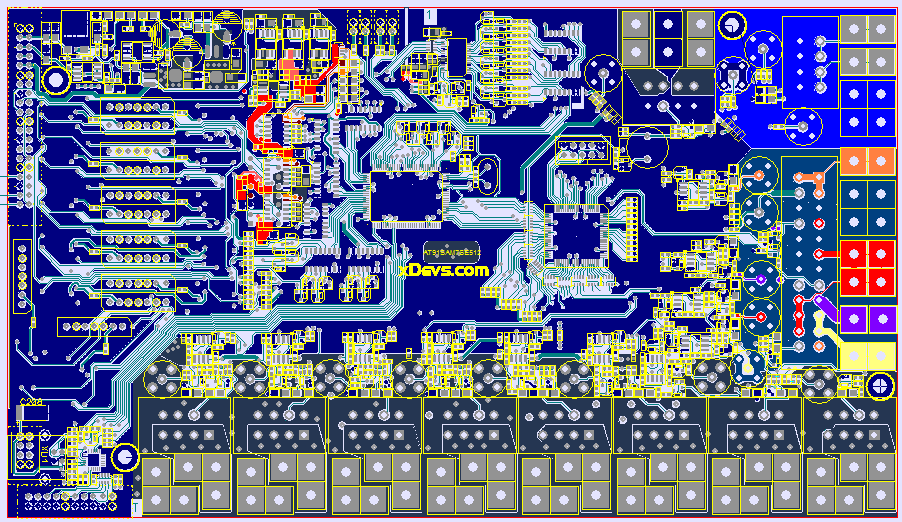
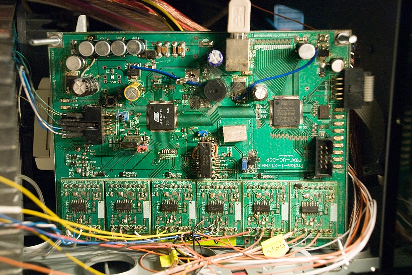
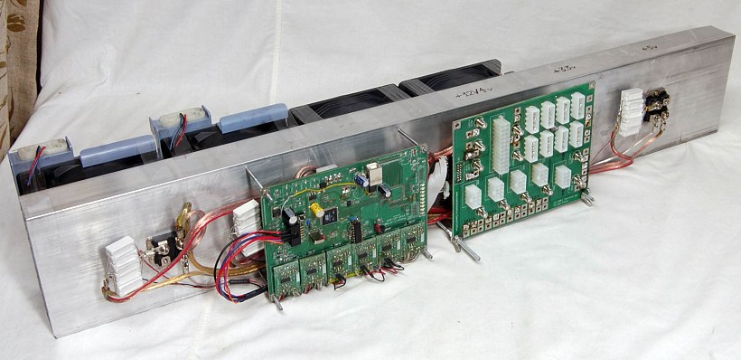
Nice 4-layer PCB now, with all connector front end and measurement circuitry on same board. The only thing left externally are actual power MOSFETs with their current shunt resistors.
Software was revamped too, with great help by friend of mine, which works as back-end web developer and have no idea about any of embedded stuff

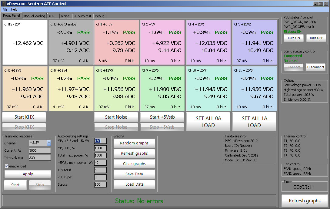
As a result, whole thing was making pretty graphs like this one:
All design details, schematics, firmwares, softwares, dozens of photos and files for grabs are available in
article on my site.
Hope you like it


